
User's Manual
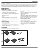

Control and Connection Panels
8 - English
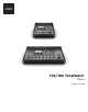
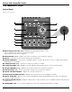
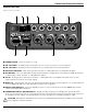
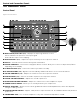
T8S ToneMatch® Mixer
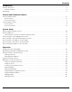
Control Panel
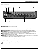
Figure 3. T8S Control Panel
q INPUT SIGNAL/CLIP LEDs (1-8) – Displays the input signal status in color:
Green: Indicates the presence of an input signal
Red: Indicates input source clipping
w TRIM CONTROLS (1-8) – Adjusts the input sensitivity for the respective channel.
e DISPLAY – Provides function menus and system information.
r EDITING CONTROLS – These three rotary/push-button controls allow you to select or adjust items/values
appearing on the display.
t CH EDIT BUTTONS (1-8) – Selects the channel you want to modify.
y FX MUTE BUTTONS (1-8) – Bypasses the Mod, Delay, and Reverb eects on the selected channel.
u VOLUME CONTROLS (1-8) – Adjusts the volume level for the respective channel.
i MUTE BUTTONS (1-8) – Silences the audio output for the respective channel.
o MASTER VOLUME CONTROL – Adjusts the overall output level.
a HEADPHONE VOLUME CONTROL – Adjust the volume level of the headphone output.
s STEREO OUTPUT METER – Allows you to visually measure your output level.
d ROTARY SELECTOR – Allows access to both global and channel-related parameters, which are adjusted
using the editing controls.
f PHANTOM POWER SWITCH – Applies +48V power to input channels 1-8. A red LED indicates that phantom
power is on.
g HEADPHONE JACK – For use with headphones only, with a minimum impedance of 24Ω.
q
w
i
o
g
a
s
d
f
u
y
t
r
e