AUDIO VIDEO SURROUND RECEIVER KR-897 KR-797 INSTRUCTION MANUAL KENWOOD CORPORATION This manual contains instructions for two models. Model availability and features (functions) may differ depending on country and sales area. Model KR-897 is not available in except for U.S.A. and Canada. B60-3069-00 CS (K, P, Y) MC 98/12 11 10 9 8 7 6 5 4 3 2 1 97/12 11 10 9 8 7 6 5 4 3 2 1 KR-897_797(En).pm5 1 07.6.
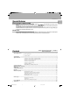
Before applying power KR-897/KR-797 (En) 2 Before applying power 3 Caution : Read this section carefully to ensure safe operation. Units are designed for operation as follows. U.S.A. and Canada ........................................... AC120 V only Australia ....................................................... AC 240 V only Europe and U.K. .............................................. AC 230 V only China and Russia ............................................ AC 220 V only *Other countries .....
KR-897/KR-797 (En) Special features 3 DOLBY PRO LOGIC & DOLBY 3 STEREO The surround system reproduces video software programs carrying the mark with similar acoustic effects to movie theaters. The DOLBY PRO LOGIC mode controls the audio signals of the Front Left/Right, Center and Rear surround channels using the built-in directivity enhancer circuit to reproduce the feeling of sound motions very realistically.
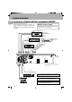
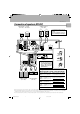
System connection KR-897/KR-797 (En) 4 Connections of Audio and Video components (KR-897) Make connection as shown below. When connecting the related system components, refer also to the instruction manuals of the related components. 3 Do not plug in the power lead until all connections are completed. Malfunction of microcomputer If operation is not possible or erroneous display appears even though all connections have been made properly, reset the microcomputer referring to “In case of difficulty”.
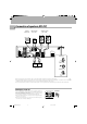
System connection KR-897/KR-797 (En) Connections of Audio and Video components (KR-797) Make connection as shown below. When connecting the related system components, refer also to the instruction manuals of the related components. 3 Do not plug in the power lead until all connections are completed. Malfunction of microcomputer If operation is not possible or erroneous display appears even though all connections have been made properly, reset the microcomputer referring to “In case of difficulty”.
KR-897/KR-797 (En) 6 About the system control connections Connecting system control cords after connecting a KENWOOD audio component system lets you take advantage of convenient system control operations. There are two KENWOOD system control modes. Make connections according to the groups of terminal symbols shown below. ƒ Mode: lets you combine F , f , and Mode: for terminals only ƒ terminals This unit is compatible with both [XS8] and [SL16] modes. It comes from the factory set to the [SL16] mode.
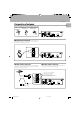
KR-897/KR-797 (En) Connection of speakers (KR-897) Center speaker Powerd (8Ω ~ 16Ω) sub-woofer 7 Speaker system A (8Ω ~ 16Ω) R L * Connect the speakers for use in surround play to speaker system A. Speaker system B does not output sound during surround play.
KR-897/KR-797 (En) 8 Connection of speakers (KR-797) Powerd sub-woofer Center speaker (8Ω ~ 16Ω) Speaker system (8Ω ~ 16Ω) R ª VIDEO 2 PLAY IN REC OUT TAPE 2 MONITOR ANTENNA AM L R L PLAY IN R CD R L R · FRONT SPEAKERS ( 8−16Ω) C + L SUBWOOFER PRE OUT ª SURROUND SPEAKERS ( 4−8Ω) · CENTER SPEAKER ( 8−16Ω) · SWITCHED + − (ƒ) AUDIO ª IN VIDEO 1 SYSTEM /TAPE 1 CONTROL PHONO ª ADAPTOR REC OUT GND FM 75Ω L R OUT PLAY IN FM 300Ω · · L − R 1 Push lever.
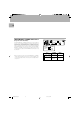
KR-897/KR-797 (En) Connection of antenna 9 Connection method to each antenna terminal 1 Push lever. 2 Insert cord. 3 Return lever. VIDEO 2 PLAY IN L L REC OUT R R TAPE 2 MONITOR ANTENNA OUT AM PLAY IN FM 300Ω L R REC OUT FRONT SPEAKERS ( 8−16Ω) C + VIDEO 1 SYSTEM /TAPE 1 CONTROL PHONO GND PLAY IN L SWITCHED + − − CD R FM 75Ω IN ADAPTOR ƒ SURROUND SPEAKERS ( 4−8Ω) SUBWOOFER PRE OUT L R AUDIO CENTER SPEAKER ( 8−16Ω) L R The illustration shows the KR-797.
KR-897/KR-797 (En) 10 FM DE-EMPHASIS / CHANNEL SPACE switch (Except for U.S.A. and Canada) ANTENNA 75μs AM 10kHz FM 100kHz DE− EMPHASIS CHANNEL SPACE 50μs AM 9kHz FM 50kHz L R L AC 110120V∼ OUT PLAY IN FM 300Ω ADAPTOR R KR-897_797(En).
Controls and indicators KR-897/KR-797 (En) 11 SURROUND indicator 3 STEREO indicator MEMORY indicator Source Direct indicator TAPE 2 indicator 3 STEREO SURROUND TAPE 2 N.B. ST. AM FM N.B. circuit indicator Broadcast band indicators * * * * * * ;* * 1 M kHz MHz Display 3 4 2 AUTO TUNED AUTO tuning/AUTO stereo reception indicator Frequency display, Input display, Preset channel display, Surround mode display STEREO indicator S.
Operation of remote control unit KR-897/KR-797 (En) 12 Names of keys and their functions The remote control unit provided with the receiver can also control KENWOOD cassette decks, MULTIPLE CD player and MD recorder connected to the recieiver through system control cords. For details of the controllable functions, refer to the instruction manuals of these components. Model: RC-R0505 Infrared ray system Numeric keys POWER key Used as the numeric keys of the input source component being selected.
KR-897/KR-797 (En) Operation procedure 13 1 Switch ON the power of the main unit. Select the component to be remote controlled 2 with one of the controlled component selection 3 ÷ Pressing the POWER key of the remote control unit while the STANDBY indicator is lit turns the power ON. Press the desired key after the power has been turned ON. ÷ When two operation keys of the remote control unit are pressed successively, press each key securely reserving an interval of more than 1 second for each press.
Playing music KR-897/KR-797 (En) 14 POWER 1 2 3 4 5 6 0 7 8 9 +10 DISK SKIP A/B +100 7 2 6 AUTO BAND 1 ¡ 4 VIDEO1 TAPE1 TUNER CD PHONO VIDEO2 TAPE2 MONITOR AV AUX MUTE ¢ AUDIO-VIDEO SURROUND RECEIVER KR-897 PRO LOGIC SRS 3D SPEAKERS 1 2 SOUND 3 4 5 6 7 8 9 0 SRS 3D N.B. SOURCE DIRECT INPUT SELECTOR VOLUME CONTROL +10 ON/STANDBY AUTO LEVEL CONTROL STEREO STANDBY POWER LISTEN MODE CENTER MODE SETUP 3 STEREO P.
Sound adjustment functions KR-897/KR-797 (En) 1 2 3 POWER 4 5 6 0 8 9 DISK SKIP 7 2 A/B +100 7 AUTO 15 +10 6 BAND 1 ¡ 4 VIDEO1 TAPE1 TUNER CD PHONO VIDEO2 TAPE2 MONITOR AV AUX MUTE ¢ AUDIO-VIDEO SURROUND RECEIVER KR-897 PRO LOGIC SRS 3D SPEAKERS 1 2 AUTO LEVEL CONTROL STEREO SRS 3D N.B. SOURCE DIRECT INPUT SELECTOR VOLUME CONTROL STANDBY POWER LISTEN MODE CENTER MODE SETUP 3 STEREO P.
KR-897/KR-797 (En) 16 POWER 1 2 3 4 5 6 0 7 8 9 +10 DISK SKIP A/B +100 7 2 6 AUTO BAND 1 ¡ 4 VIDEO1 TAPE1 TUNER CD PHONO VIDEO2 TAPE2 MONITOR AV AUX MUTE ¢ AUDIO-VIDEO SURROUND RECEIVER KR-897 PRO LOGIC SRS 3D SPEAKERS SRS 3D N.B. SOURCE DIRECT INPUT SELECTOR VOLUME CONTROL POWER 1 LISTEN MODE 2 SOUND 3 4 5 6 7 8 9 0 +10 ON/STANDBY AUTO LEVEL CONTROL STEREO STANDBY CENTER MODE SETUP 3 STEREO P.
KR-897/KR-797 (En) 1 2 3 POWER 4 5 6 0 8 9 DISK SKIP 7 2 A/B +100 7 AUTO 17 +10 6 BAND 1 ¡ 4 VIDEO1 TAPE1 TUNER CD PHONO VIDEO2 TAPE2 MONITOR AV AUX MUTE ¢ AUDIO-VIDEO SURROUND RECEIVER KR-897 PRO LOGIC SRS 3D SPEAKERS 1 2 SOUND 3 4 5 6 7 8 9 0 SRS 3D N.B. SOURCE DIRECT INPUT SELECTOR VOLUME CONTROL +10 ON/STANDBY AUTO LEVEL CONTROL STEREO STANDBY POWER LISTEN MODE CENTER MODE SETUP 3 STEREO P.
Recording KR-897/KR-797 (En) 18 When recording sound with a recorder component of KENWOOD, synchro recording is possible by setting the INPUT SELECTOR to select TAPE1 or MD according to the connected component. Preparation ÷ Switch the TAPE1 display to MD or VIDEO1 with the following operation. 1 Select TAPE1 with the INPUT SELECTOR. 2 Press and hold the AUTO key for more than 2 seconds. Each press switches the display.
Broadcast reception KR-897/KR-797 (En) 1 2 3 POWER 4 5 6 0 8 9 DISK SKIP 7 2 A/B +100 7 AUTO 19 +10 6 BAND 1 ¡ 4 VIDEO1 TAPE1 TUNER CD PHONO VIDEO2 TAPE2 MONITOR AV AUX MUTE ¢ AUDIO-VIDEO SURROUND RECEIVER KR-897 PRO LOGIC SRS 3D SPEAKERS 1 2 3 SOUND 4 5 6 7 8 9 SRS 3D N.B. SOURCE DIRECT INPUT SELECTOR VOLUME CONTROL +10 0 ON/STANDBY AUTO LEVEL CONTROL STEREO STANDBY POWER LISTEN MODE CENTER MODE SETUP 3 STEREO P.
KR-897/KR-797 (En) 20 POWER 1 2 3 4 5 6 0 7 8 9 +10 DISK SKIP A/B +100 7 2 6 AUTO BAND 1 ¡ 4 VIDEO1 TAPE1 TUNER CD PHONO VIDEO2 TAPE2 MONITOR AV AUX MUTE ¢ AUDIO-VIDEO SURROUND RECEIVER KR-897 PRO LOGIC SRS 3D SPEAKERS 1 2 3 SOUND 4 5 6 7 8 9 0 SRS 3D N.B. SOURCE DIRECT INPUT SELECTOR VOLUME CONTROL +10 ON/STANDBY AUTO LEVEL CONTROL STEREO STANDBY POWER LISTEN MODE CENTER MODE SETUP 3 STEREO P.
KR-897/KR-797 (En) Preparation ÷ Select the TUNER input. 1 2 3 POWER 4 5 6 0 8 9 DISK SKIP 7 2 A/B +100 7 AUTO 21 +10 6 BAND 1 ¡ 4 VIDEO1 TAPE1 TUNER CD PHONO VIDEO2 TAPE2 MONITOR AV AUX MUTE ¢ AUDIO-VIDEO SURROUND RECEIVER KR-897 PRO LOGIC SRS 3D SPEAKERS 1 2 SOUND 3 4 5 6 7 8 9 0 SRS 3D N.B. SOURCE DIRECT INPUT SELECTOR VOLUME CONTROL +10 ON/STANDBY AUTO LEVEL CONTROL STEREO STANDBY POWER LISTEN MODE CENTER MODE SETUP 3 STEREO P.
KR-897/KR-797 (En) 22 KR-897_797(En).pm5 22 07.6.
Presence play KR-897/KR-797 (En) The surround modes allow you to enjoy the feeling of presence in music. Select the mode according to the source or components played. For the connections of the surround and/or center speakers, refer to “Connection of speakers”. 78 DOLBY PRO LOGIC surround mode In case center speaker is not used Video, DVD and LD software programs carrying the mark contain recording of the same Dolby Surround data as those used in movie theaters.
KR-897/KR-797 (En) 24 To improve the feeling of presence in the surround modes, various parameters of each surround mode can be set up according to the speaker system used as well as to the environmental of the listening room. The following procedure let you set the parameters of the surround mode (DOLBY PRO LOGIC, DOLBY 3 STEREO). Once the settings have been done, it is held in memory so readjustment is not necessary even after the mode has been changed to other modes.
KR-897/KR-797 (En) How to calculate the proper delay time Assuming that the distance from the front speakers is A meters and that from the surround speakers is B meters: Front speakers Example: When A = 3 m,B = 3 m, the delay time is 20 ms. Am 8 Bm Surround speakers What is delay time? 1 Use the delay time calculation chart on the right. 29 29 29 7 2 Use the following formula for calculation.
KR-897/KR-797 (En) 26 When playing videotape (DVD or LD) software carrying the mark, a sound field with enhanced surround effects can be enjoyed by using the DOLBY PRO LOGIC or DOLBY 3 STEREO mode. Be sure to complete “Adjustments for surround play” prior to starting playback in one of these surround modes.
KR-897/KR-797 (En) The Sound Retrieval System is an epochal system which produces a three-dimensional sound space by applying the most suitable processing to the sound signal on the basis of the human listening mechanism. This permits real depth and sound location, considered as difficult to realize with conventional 2-channel stereo (general stereo). A sufficient effect can be obtained for any source (CD, tape, broadcasts, etc.).
In case of difficulty KR-897/KR-797 (En) 28 What appears to be a mulfunction may not always be serious. If your unit should not perform as expected, consult the table below to see if the problem can be corrected before seeking help from your dealer or service representative. Operation to reset 1 Unplug the AC power plug from the wall outlet. 2 While holding the POWER switch depressed, plug the AC plug into the power outlet.
KR-897/KR-797 (En) 29 Remote control unit Cause Remedy ÷ Batteries are exhausted. ÷ The remote control unit is too far away from the main system, controlling angle is too large, or there is an obstacle in between. ÷ The audio cords and system control cords are not connected properly. ÷ The source component to be operated does not contain the tape(s) or CD. ÷ An attempt is made to play a tape which is being recorded in the cassette deck. ÷ Replace with new batteries.
Specifications of KR-797 (for U.S.A. and Canada) KR-897/KR-797 (En) 3Caution : Read this page carefully to ensure safe operation. 30 Audio section FM Tuner section Rated power output at the STEREO operation Tuning frequency range ...................... 87.5 MHz ~ 108 MHz Usable sensitivity MONO ....................................... 1.3 µV (at 75 Ω) / 13.2 dBf (75 kHz dev., SINAD 30 dB) 50 dB quieting sensitivity STEREO ..................................... 31.6 µV (at 75 Ω) / 41.
Specifications of KR-797 (for ohter countries) KR-897/KR-797 (En) 3Caution : Read this page carefully to ensure safe operation. Audio section FM Tuner section Rated power output at the STEREO operation Tuning frequency range ......................... 87.5 MHz~108 MHz Usable sensitivity MONO .......................................... 2.0 µV (at 75 Ω) / 17.2 dBf (75 kHz dev., S/N 30 dB) 50 dB quieting sensitivity STEREO ....................................... 35 µV (at 75 Ω) / 42.
Specifications of KR-897 (for U.S.A. and Canada) KR-897/KR-797 (En) 3Caution : Read this page carefully to ensure safe operation. 32 Audio section FM Tuner section Rated power output at the STEREO operation Tuning frequency range ...................... 87.5 MHz ~ 108 MHz Usable sensitivity MONO ....................................... 1.3 µV (at 75 Ω) / 13.2 dBf (75 kHz dev., SINAD 30 dB) 50 dB quieting sensitivity STEREO ..................................... 31.6 µV (at 75 Ω) / 41.