LIFESTYLE® DVD Home Entertainment Systems Installation Guide April 23, 2002 AM259777_02_V.
Safety Information WARNING: To reduce the risk of fire or electric shock, do not expose the system to rain or moisture. CAUTION A VIS RISK OF ELECTRICAL SHOCK DO NOT OPEN RISQUE DE CHOC ÉLECTRIQUE NE PAS OUVRIR CAUTION: TO REDUCE THE RISK OF ELECTRIC SHOCK, DO NOT REMOVE COVER (OR BACK). NO USER-SERVICABLE PARTS INSIDE. REFER SERVICING TO QUALIFIED PERSONNEL. AFIN DE PRÉVENIR UN CHOC ÉLECTRIQUE NE PAS ENLEVER LE COUVERCLE ARRIÈRE.
Contents Where to find … Introduction . . . . . . . . . . . . . . . . . . . . . . . . . . . . . . . . . . . . . . . . . . . . . . . . . . . . . . . . . . . . . . . . . . . . . . . Welcome . . . . . . . . . . . . . . . . . . . . . . . . . . . . . . . . . . . . . . . . . . . . . . . . . . . . . . . . . . . . . . . . . . . Region numbers . . . . . . . . . . . . . . . . . . . . . . . . . . . . . . . . . . . . . . . . . . . . . . . . . . . . . . . . . . . . . Types of discs you can play . . . . . . . . . . . . .
Introduction Welcome Thank you for purchasing a LIFESTYLE® home entertainment system. If you have successfully installed your new LIFESTYLE® system using the Quick Set Up Guide, congratulations! You can now skip to “Finishing the installation” on page 21. If not, the information provided on the following pages will guide you through the installation. Region numbers Region numbers are assigned to DVD players and discs according to where they are sold.
System Installation Getting started After unpacking your new system, save all packing materials. The original packing materials provide the safest way to transport your system if necessary. If any part of your system is missing or appears damaged, contact your authorized Bose® dealer immediately, or contact Bose directly. Refer to the Bose address list included with your system. The instructions in this section tell you how to connect your system as shown in Figure 1.
System Installation Instructions Cables and accessories The following items are included with your system.
System Installation Instructions Placing your speakers When you place your speakers according to the guidelines below, a combination of reflected and direct sound provides the audio atmosphere of a home theater. You may experiment with the placement and orientation of the speakers to produce the sound most pleasing to you. CAUTION: Choose a stable and level surface for your speakers. Vibration can cause the speakers to move, particularly on smooth surfaces like marble, glass, or highly polished wood.
System Installation Instructions Figure 4 Left front Speaker placement and reflection rays Center Right front Acoustimass® module Left surround Right surround Center speaker placement The sound from the center speaker should appear to come directly from the center of the picture. The center speaker cable allows up to 20 feet (6.1 m) distance from the Acoustimass module. 1. Place the center speaker directly above or below the center of the TV screen, or at the closest convenient location.
System Installation Instructions Acoustimass® module placement Note: Now is a good time to find the serial number on the bottom of the module, before you proceed. Copy that number onto your warranty card and in the space provided on page 2 of this guide. Follow these guidelines to select a location for the Acoustimass module: • Place the Acoustimass module along the same wall as the TV, or close to the same end of the room as the front speakers (see Figure 4).
System Installation Instructions Placing your media center Note: Now is a good time to find the serial number on the bottom of the media center, before you proceed. Copy that number onto your warranty card and in the space provided on page 2 of this guide. Select a location for the media center, keeping in mind the following guidelines: • Do not block the front of the media center. Make sure you allow enough room to lift up the front cover and open the CD tray of the CD/DVD player.
System Installation Instructions Connecting the speakers to the Acoustimass® module Note: Before you start making system connections, make sure that the media center, the Acoustimass module, and any additional equipment are not connected to AC power. The five dual-cube speakers that come with your system will either have a two-wire cable connector (Figure 7) or a plug-in cable connector (Figure 8 on page 12). Identify your type of speaker and then follow the corresponding instructions.
System Installation Instructions Making a plug-in cable speaker connection In a plug-in cable connection (Figure 8), the positive and negative wires are oriented to ensure proper polarity. Figure 8 A plug-in cable type speaker 3 1. Match the correct cable to the corresponding speaker location. Front speaker cables have blue RCA connectors at one end, with L (left), R (right), or C (center) molded into both the RCA connectors and the speaker connectors at the other end.
System Installation Instructions Connecting the Acoustimass® module to the media center Connect the Acoustimass module to the media center with the audio input cable (Figure 10). Note: Be sure that each connector is fully inserted into each jack. 1. Plug the small black multi-pin connector (flat side facing up) into the SPEAKER ZONES jack labeled “1” on the back of the media center. 2.
System Installation Instructions Connecting the antennas The rear panel of the media center provides connections for AM and FM antennas (Figure 11). Be sure to unwrap the bundled antenna wires and straighten them as much as possible to ensure the best reception. Note: Outdoor antennas may be used. To install an outdoor antenna, consult a qualified installer. Follow all safety instructions supplied with the antenna.
System Installation Instructions Connecting your TV to the system The media center provides audio and video connections for your TV. See Figure 12. Making audio connections 4 Using the supplied stereo audio cable, connect the left (L) and right (R) audio outputs on the rear panel of your TV to the L and R TV audio inputs on the rear panel of the media center (Figure 12). Making video connections These connections will vary according to the type of cable you use as described below.
System Installation Instructions To make component video connections, you will need video-grade cables for the Y, Pb, and Pr jacks and the Bose® component video adapter (Figure 13). This adapter plugs into the S-VIDEO and COMPOSITE outputs. Your system will send the correct signals to these jacks when you change the video output setting to YPbPr. See your LIFESTYLE® 28/35 system operating guide for instructions on how to change system settings.
System Installation Instructions Connecting your cable/satellite box to the system (optional) The type of video connection used with your TV and VCR must match the type of connection used with your cable/satellite box, if you choose to connect it to the system. If you connected your TV to the COMPOSITE VIDEO OUTPUT, connect your cable/satellite box output to the COMPOSITE VIDEO INPUT. If you connected your TV to the S-VIDEO OUTPUT, connect your cable/satellite box to the S-VIDEO INPUT.
System Installation Instructions Installing the TV on/off detector (optional) The TV on/off detector senses whether your TV is on or off. This enables the media center to automatically switch the TV on, as needed, when another video source (DVD, cable/satellite box, etc.) is selected. If you choose not to use the sensor, you will need to turn the TV on separately each time it is needed.
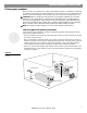
System Installation Instructions Making the temporary headset connection before connecting to power Plug the special headset connector into the AUX jacks on the rear of the media center (Figure 17). This is for temporary use during steps for “Finishing the installation” on page 21. Figure 17 RECORD AUX TAPE VCR TV 33V DC POWER 1.
System Installation Instructions Figure 19 DC power jack Power connection of the media center Power supply Rear panel Plug the small round connector of the media center power supply cable into the DC POWER jack on the back of the media center (Figure 19). Insert the power supply line cord connector into the power supply and plug the cord into an AC (mains) outlet. Installing the remote control batteries Slide the battery compartment cover off of the back of the remote.
System Installation Instructions Finishing the installation Included with your system is a small carton containing two setup discs and a special headset. 1 Figure 21 2 Contents of the small carton • Setup Disc 1 verifies that your system’s speakers are connected correctly and ensures complete performance from your new system. • Setup Disc 2 leads you through an important custom equalization process, which tailors the sound of your LIFESTYLE® system for the acoustics of your listening area.
System Installation Instructions Save the headset for possible future use When you have played both discs and followed their instructions, the installation of your LIFESTYLE® DVD system is completed and its performance is tailored to your particular listening area. Moving the system to another room or significantly changing the arrangement of the room (relocating seating, furniture, speakers or the Acoustimass® module) will change your listening environment.
Reference Using alternate system connections The following describes alternate ways to connect your VCR and TV to your LIFESTYLE® home entertainment system. To play VCR audio (not TV audio) through your system Connect the VCR audio outputs to the TV or VCR inputs of the media center as in Figure 1 on page 5, but do not connect the TV audio outputs. In this configuration, your VCR audio is played through your system, but the TV audio is played directly from the TV.
Reference To play TV audio through your system with VCR audio fed to the TV Connect the VCR audio outputs to the audio inputs of the TV. Connect the TV audio outputs to the TV inputs on the media center. In this configuration, the LIFESTYLE® system TV source must always be selected.
Reference Setting up a second listening zone Your LIFESTYLE® home entertainment system can direct sound from one or two sound sources (such as CD, AM/FM tuner, TAPE, or AUX) to two different listening zones at the same time. What is a zone? Each listening area, whether a room or a group of rooms (including outdoor areas), is called a zone. Your primary listening area is set up as zone 1.
Reference Connecting external equipment Other equipment can be connected to your system using standard RCA audio cables. Be sure to match the red connector to the R (right) channel and the white (or black) connector to the L (left) channel. A Y adapter can be used to connect mono sources. The appropriate cables are available at most electronic stores. Connecting record/playback equipment The rear panel of the media center provides input (TAPE) and output (RECORD) connections for a cassette tape deck.
Reference Connecting other playback equipment Other playback components such as an audio CD changer can be connected to the AUX inputs on the rear panel of the media center. Figure 26 AUX input connections RECORD TV SENSOR AUX TAPE VCR TV 33V DC POWER 1.
Reference Connecting the optional IR emitter cable The IR (infrared) emitter cable is designed for optional use with system components that are connected to the media center, but placed where they cannot receive IR signals from it. This can resolve the problem when a particular component does not respond to LIFESTYLE® remote control commands. By plugging an emitter into the media center and placing it near the component, you can make sure that the LIFESTYLE® remote control signals reach that component.
Reference Technical information Media Center power pack power rating USA/Canada: 120V 0.55A 50/60 Hz 33VDC 1.1A Speaker system power rating USA/Canada: 100-120V 50/60 Hz 350W Media center inputs TAPE: 2Vrms, maximum AUX: 2Vrms, maximum VCR: 2Vrms, maximum TV: 2Vrms, maximum DIGITAL: SPDIF (1 each for TV, VCR, TAPE, and AUX) COMPOSITE VIDEO: NTSC or PAL format 1Vp-p with sync 75 Ω S-VIDEO: Luminance 1Vp-p, Chrominance 0.
AM259777_02_V.
AM259777_02_V.
©2002 Bose Corporation, The Mountain, Framingham, MA 01701-9168 USA 259777 AM Rev.02 JN21093 AM259777_02_V.