Bose® Virtually Invisible® 191 Speakers May 13, 2003 AM267565_00_V.
Safety Information Important words of caution WARNING: Installation shall be in accordance with the applicable section of the National Electrical Code, ANSI/NFPA 70, and/or the National Fire Alarm Code, ANSI/NFPA 72, as applicable. The wiring method and compartment shall be such as not to interfere with the operation of the speaker. CAUTION: Consult local building codes before you get started with this installation. Please read this owner’s guide completely before you start.
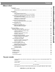
Contents Where to find... 15 15 15 15 17 18 20 20 21 21 22 23 24 26 26 28 29 29 29 30 31 Reference . . . . . . . . . . . . . . . . . . . . . . . . . . . . . . . . . . . . . . . . . . . . . . . . . . . . . . . . . . . . . . . . . . . . . Troubleshooting . . . . . . . . . . . . . . . . . . . . . . . . . . . . . . . . . . . . . . . . . . . . . . . . . . . . . . . . . . . . Customer service . . . . . . . . . . . . . . . . . . . . . . . . . . . . . . . . . . . . . . . . . . . . . . . . . . . . . . . . . . .
Introduction Before you begin... Please be sure to read this guide carefully before you do any cutting. There are many factors to consider when choosing a location for your speakers. Thank you for choosing to install Bose® Virtually Invisible® 191 speakers in your room. Innovative engineering and advanced design enable these speakers to deliver Bose quality performance for big impact in spite of their small size.
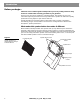
Preparation Unpacking Carefully unpack the speakers. Save all packing materials, which provide the safest means to transport your speakers as needed. If any part of the speaker pair appears damaged, do not use the pair. Notify Bose or your authorized Bose® dealer immediately. For Bose contact information, refer to the address list included in the carton. Check to be sure the carton includes all the parts shown in Figure 2. Note: Now is a good time to find the serial numbers on the side of each speaker.
Preparation Wear clothing appropriate for the job, and consider using a drop cloth or other material to protect the area from debris. How and where you install the speakers will determine your need for optional equipment.
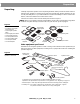
Preparation Accessories that can help For installation in a drop ceiling (where tile is installed below the ceiling joists), Bose offers an optional Drop Ceiling Kit (Product Code #031355) for two speakers. It protects the tile from bearing the weight of the speakers. Instructions are included with the kit. For installation in new construction, Bose offers a Rough-in Kit (Product Code #031353) for two speakers.
Preparation Installing in an exterior wall If you choose to install these speakers in an exterior wall (abutting the outside of your house), you will undoubtedly encounter insulation behind the wallboard. This can complicate the installation, requiring you to trim and push malleable insulation out of the way. You will need to wear eye protection and gloves for working with fiberglass insulation. WARNING: If you believe the insulation inside a wall may be composed of asbestos, do not cut into the wall.
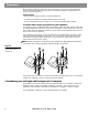
Preparation Select the general wall area for one speaker As you decide where you want each speaker grille, use the guidelines below: CAUTION: Do not install near any heat sources, such as halogen lamps, registers, stoves, or other apparatus (including amplifiers) that produce heat. • The two speakers should be a minimum of 5 feet (1.5 m) apart. • For in-wall speakers providing stereo at the front of the room or home theater surround sound from the rear, install them so each speaker grille is 4 to 6 feet (1.
Preparation • Each speaker enclosure extends into the wall or ceiling, as shown in the gray DO NOT CUT area on the template (Figure 7), and below the grille. The speaker enclosure can be inserted either up or down. Note: In cold climates where a humidifier is used, avoid inserting the speaker upside-down in an exterior wall to prevent problems with condensation.
Preparation Using speaker cord Before you cut any cord, estimate how much will be needed for each speaker. To do so, measure the distance from the receiver/amplifier to where each speaker will be installed. Make some allowance if the cord must go around corners or through walls, and leave at least 14 inches (36 cm) of cord to pull from the wall for making the connections easily.
Preparation You also need to observe safe and practical standards: WARNING: Make sure the spot chosen is safe for drilling. Do not drill through surfaces that may have hazards, such as electrical wiring, conduits, or plumbing concealed behind them. Follow all other safety precautions. • Consult local building codes to inform yourself of the requirements in your area. • Use a drill bit large enough for the cord you will pull through the holes.
Preparation Before the wallboard goes up There are some standard guidelines for working in unfinished construction. • Begin this work after the studs and joists are in and the electrical wiring is completed. • Snap a chalk line across the face of the studs or the bottom of the joists and move backward as you drill, so you can keep the last hole drilled in your line of sight. • Never run speaker cord and electrical cable through the same hole or into the same junction box.
Preparation Getting started Choose a path for the cord that avoids impediments to drill through. Use a stud finder to identify inaccessible studs. It is common to run cord from the speaker location in a wall or ceiling to the attic and through the wooden top plate that runs horizontally across the top of the vertical studs. From the attic, you can then run the cord to the spot above the junction box near the receiver or amplifier.
Steps to Installing Before you make any holes Be sure you have read and understand the considerations provided in “Preparation” starting on page 5, so you can proceed with confidence. Installation is basically the same, whether you are using these speakers with a rectangular grille or round grille and installing in a wall or ceiling. There are a few exceptions. Wherever special instructions apply to ceiling or round-faced speaker installation, those instructions will appear in a gray box, like this.
Steps to Installing 2. Center the pilot-hole circles on the selected spot as you press the template to the wall. 3. Use a pencil to trace around the inside of the circles (Figure 14). Round-faced speakers require additional clearance holes on either side of the speaker hole. Draw those circles as well as the pilot hole circles now.
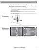
Steps to Installing Drilling the pilot hole You will need a half-inch spade bit and power drill, or a special rotary cutting tool for this step. Using the proper equipment and protection is important. WARNING: Use eye protection and be sure to observe all safety precautions while using the drill or cutting tool (Figure 15). Figure 15 Caution against drilling without eye protection WARNING: Make sure the spot chosen is safe for cutting.
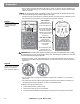
Steps to Installing Testing the space behind the hole You need a tape measure and a sturdy wire (such as a straightened coat hanger) 22 inches (55.9 cm) in length for this step. 1. Bend the wire as shown in Figure 17. Figure 17 A 22-inch (55.9 cm) length of sturdy wire bent in two places 3 inches (7.6 cm) 141/4 inches (36.2 cm) 41/8 inches (10.5 cm) 43/4 inches (12 cm) Tip: For greater accuracy, make the first bend a little long, measure again, and cut off the extra length at that end.
Steps to Installing Figure 19 Checking the space for the width of the speaker 360˚ • If the wire goes around the 360˚ arc without a problem, proceed to step 5 below. Round-faced speakers require an additional 2 inches of clearance above the speaker. • If you cannot rotate the wire all the way around up to the first bend, you need to drill a new pilot hole elsewhere. Then repeat the preceding steps 3 and 4. Now remove the wire. 5.
Steps to Installing Note: To position the logo right-side-up if you insert the speaker upside-down, remove the outer frame from the face of the speaker, rotate it 180˚, then reattach the frame. There are four speaker frame screws, labeled GRILLE, that hold the frame in place. They should not be confused with the dogleg clamp screws that are labeled WALL (Figure 21). Those screws hold the dogleg clamps on the frame.
Steps to Installing Prepare the wall for inserting the speaker Use care in the steps that follow to ensure satisfaction with the end result. CAUTION: Now is a good time to reconsider your comfort level with this job. If you have doubts about cutting into or running cord behind the wall, it’s best to stop here. Then you can contact a professional installer, describe the job, and request a cost estimate before engaging the installer’s services.
Steps to Installing Tip: If necessary, use tape to hold the template temporarily in place (see TAPE HERE on the template). Then run your pencil along the entire template edge, except where there is tape. For ceiling installation, notice the orientation of the Bose® logo on the speaker frame. Make sure it will be oriented as you want it when you position the speaker in the hole you cut.
Steps to Installing 6. Cut around three of the four sides of the outline you drew, not all the way around (Figure 24a). WARNING: Keep fingers away from the cutting blade. Figure 24 7. Hook your finger into the pilot hole and then make the final cut (Figure 24b). 8. Using your finger, pull out the piece of wallboard you have just cut.
Steps to Installing Figure 25 Pulling the wire up and out, to the left At least14 inches (36 cm) of wire 2. Use tape or the assistance of another person to temporarily affix the loose end of the wire above and to the left of the hole (Figure 26). This keeps the wire out of the way until you have the speaker partially inserted in the wall and are ready to make the connections.
Steps to Installing Figure 27 1. Use both hands to support the speaker and angle it slightly, so it is diagonal to the hole. This allows clearance for the wall stops. 2. Insert the bottom of the enclosure through the hole and down part of the way – or up, depending on your clearance issues (Figure 27). Dogleg clamps Dogleg clamps Partially inserting the rectangular-faced or roundfaced speaker Wall stop Wall stop 3.
Steps to Installing Make the speaker connections You need a Phillips-head screwdriver for this step. Tip: Pay attention to maintaining the proper polarity (+ to + and – to –) with these connections. An error here will adversely affect speaker performance. Also be sure to tighten each screw securely, but not enough to cause undesirable compression of the wire. 1. If you have not done so earlier, loosen the screws on both terminals. 2.
Steps to Installing To test the speaker: 1. Turn on the receiver/amplifier and play a piece of music that is familiar to you. 2. Listen for clarity and accuracy of the performance from one speaker. • If you hear a problem, refer to “Troubleshooting” starting on page 32. • If the performance sounds fine, test the other speaker, or continue with the installation steps for this speaker. When the connections are completed, push any excess wire into the hole behind the speaker (Figure 30).
Steps to Installing Secure the speaker to the wall CAUTION: If you use a screw gun to tighten any screws, first select the gun’s lowest torque setting (do not exceed 2-4 inch-pounds or 0.2-0.5 N-m of torque). If the screw does not seat properly, finish installing the screw at the next highest torque setting, or by hand. When the speaker is positioned inside the hole with the face straight and flat against the wall, you are ready to tighten the dogleg clamp screws, labeled WALL, along the sides of the frame.
Steps to Installing 4. Line up the curved edge of the grille with the curve over the Bose® logo and press that edge into the speaker frame first (Figure 33). 5. Press the top of the grille firmly into place until you feel some resistance. When the grille lines up flush with the frame of the speaker, it is seated properly. Figure 33 Snapping the grille into place If the speaker looks crooked When you step back from the wall, you may notice that the speaker is not straight.
Steps to Installing Painting the grille It is important to prevent paint from clogging the grille perforations, which can adversely affect performance. You can use a dry brush technique or choose to spray paint the grille. Do not use a paint roller, however. Regardless of the technique you choose: • Remove the grille from the speaker if it has been installed. • Before you begin to paint, clean the grille to remove possible contaminants. Even fingerprints can prevent uniform coverage.
Steps to Installing Steps for spray painting: 1. To prevent dirt or dried paint particles from blowing back into the grille perforations, suspend the grille or place it on a wire screen. 2. Apply the paint to the grille surface at a 45˚ angle. Then rotate the grille by 180˚ and repaint it at 45˚. Figure 34 Angling and turning used to apply the paint twice 45˚ 45˚ 180˚ Tip: Piercing a perforation with a sharp implement to remove a clog can cosmetically damage the grille and is not recommended.
Reference Troubleshooting Neither speaker plays • • Check the settings on your receiver/amplifier. Refer to the owner’s guide that came with it for instruction on settings. If your Virtually Invisible® 191 speakers are the second pair of speakers connected to your receiver/amplifier, make sure the connections have been made to the “B” terminals and that the “B” speakers are selected to play. The bass or treble is weak • • Check the tonal balance setting on your receiver/amplifier.
Reference Accessories • Drop Ceiling Kit for two speakers – PC031355 Protects the tile from bearing the weight of the speakers. Instructions included. • Rough-in Kit for two speakers – PC031353 Reserves a place for the speakers after the studs are in place and before the wallboard is added, and indicates where the wallboard hole should be made. Instructions included. For further information or to order accessories, contact your Bose® dealer.
©2003 Bose Corporation, The Mountain Framingham, MA 01701-9168 USA 267565 AM Rev. 00 JN30333 AM267565_01_V.