AmPlusTM 100 and AmPlus 50 Business Music Amplifiers Installer’s Guide
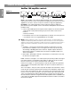
Information You Should Read English WARNING: These business music amplifiers are electrical appliances. To reduce the risk of fire or electric shock, do not expose the amplifier to rain or moisture; do not disassemble the amplifier. There are no user-serviceable parts inside. Refer servicing to qualified service personnel. The caution markings described here appear on the top of the amplifier.
Information You Should Read General cabling information Connect high impedance units, such as tape players and CD players, to the amplifier with shielded single conductor cable. Keep cable lengths shorter than 10 feet (3 m). For output loudspeaker connections, Class II wiring is suggested. Use standard #16 AWG wire. To minimize hum pick-up or other unwanted effects: • Keep loudspeaker cables away from power cables. • Use twisted shielded pairs on microphone inputs.
Information You Should Read CAUTIONS: English Always turn the amplifier power OFF before: 1. Connecting the speakers. 2. Changing the amplifier mode switch. 3. Installing the equalizer and/or option cards. Never connect the speaker output channels together. Do not connect the speaker outputs to the chassis or signal ground. Bose® recommends installation of the amplifier be performed only by an experienced and licensed contractor.
Table of Contents Information You Should Read ................................................................................... 2 Warranty period ................................................................................................... 4 Service .................................................................................................................4 How to use this guide ......................................................................................... 4 Getting Started .........
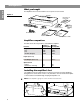
Getting Started The amplifier comes in one box and the accessory kit comes in another. Figure 1 Amplifier Declaration of Conformity CAUTION AVIS TO REDUC DO E THE RISK WARNING NOT OF FIRE OR REFER TO EXPOSE THIS ELECTRICAL OPERA YOUR INSTRU EQUIPMENT TING PROCE AND/O TO RAIN OR SHOCK, R POOR CTION PERFODURES . INCORMANUA L FOR PROPEMOISTURE. RMANC RECT WIRING E.
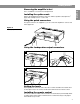
Getting Started Removing the amplifier’s feet English Use a screwdriver to loosen the foot and pull it out. Installing the option cards Refer to the installation instructions that come with the equalizer card, Opti-voice® page card, and Opti-sourceTM source card. Using the quick connectors The quick connectors are supplied so you can connect the amplifier to sources and other equipment.
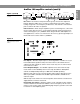
All About The AmPlusTM 100 Amplifier English AmPlus 100 amplifier controls Figure 3 AmPlus 100 amplifier controls INPUTS A INPUT MODE LEVEL Ch1 Ch2 Zone 2 Ch1 Ch2 -6 2Ch dual mono mono -10 -40 dB + - + -6 -10 REMOTE VOLUME ZONE 1 -6 ZONE 2 LINE OUTPUT ZONE 1 POWER AMPLIFIER ZONE 2 70/100V -10 0 -40 dB 0 -40 dB 0 - BASS LEVEL Ch1 Ch2 ZONE1 4-16 Ω ZONE 2 4-16 Ω XFR CT MODE OFF +10 OFF +10 + - + - + - + - + - 70/100V 2 Ch BRIDGED Inputs – The amplifier comes with two b
All About The AmPlusTM 100 Amplifier AmPlus 100 amplifier controls (cont’d) AmPlus 100 amplifier controls INPUTS A INPUT MODE LEVEL Ch1 Ch2 Zone 2 Ch1 Ch2 -6 2Ch dual mono mono -10 -40 dB + - + -6 -10 BASS LEVEL Ch1 Ch2 REMOTE VOLUME ZONE 1 -6 ZONE 2 LINE OUTPUT ZONE 1 POWER AMPLIFIER ZONE 2 70/100V -10 0 -40 dB 0 -40 dB 0 ZONE1 4-16 Ω ZONE 2 4-16 Ω XFR CT MODE OFF +10 OFF +10 - + - + - + - + - + - 70/100V 2 Ch BRIDGED Bass Level – Use the bass level potentiometers (
AmPlusTM 100 Amplifier Configurations English AmPlus 100 Amplifier Direct-coupled Model 1B Installation Source Left 1 Right 1 Right 2 Left 2 Model 1B Module AmPlus™100 Amp Remote Volume Control INPUTS A INPUT MODE LEVEL BASS LEVEL Ch1 Ch2 Ch1 Ch2 Zone 2 Ch1 -6 Ch2 2Ch dual mono -10 - + -6 ZONE 2 ZONE 1 POWER AMPLIFIER ZONE 2 ZONE 1 4-16 Ω 70/100V -10 OFF 0 -40 dB 0 -40 dB 0 ZONE 2 4-16 Ω XFR CT MODE +10 OFF +10 - + 1. First, adjust Ch.
AmPlusTM 100 Amplifier Configurations AmPlus 100 Amplifier 70/100V/Model 1B Installation English Source AmPlus™ 100 Model 1B Module Remote Volume Control INPUTS A INPUT MODE LEVEL BASS LEVEL Ch1 Ch2 Zone 2 Ch1 -6 Ch2 2Ch dual mono -10 -6 -10 - + REMOTE VOLUME LINE OUTPUT POWER AMPLIFIER Ch2 -6 ZONE 1 ZONE 2 ZONE 1 ZONE 2 70/100V ZONE 1 4-16 Ω -10 ZONE 2 4-16 Ω XFR CT MODE mono -40 dB 0 -40 dB 0 -40 dB + Ch1 0 OFF +10 OFF +10 - + - + - + - + - + - 70/100V BRIDG
AmPlusTM 100 Amplifier Configurations English AmPlus 100 Amplifier Simple Monophonic Installation Source AmPlus™ 100 Remote Volume Control INPUTS A INPUT MODE LEVEL Ch1 Ch1 Ch2 dual mono -10 - + -6 -10 -6 ZONE 1 ZONE 2 ZONE 1 POWER AMPLIFIER ZONE 2 70/100V 0 -40 dB 0 -40 dB 0 OFF +10 OFF + - + - Remote Volume Control XFR CT MODE + - + - + - 70/100V 2 Ch. BRIDGED Tap settings less than or equal to 100W Note: Both bass pots are active in this mode.
AmPlusTM 100 Amplifier Configurations AmPlus 100 Amplifier Large Monophonic Installation English Source 1 Source 2 AmPlus™ 100 Remote Volume Control AmPlus™ 100 INPUTS A INPUT MODE LEVEL BASS LEVEL Ch1 Ch2 Ch1 Ch2 Zone 2 Ch1 Ch2 -6 dual mono 2Ch - + -10 -6 ZONE 1 LINE OUTPUT ZONE 2 0 -40 dB 0 -40 dB OFF 0 +10 OFF 70/100V ZONE 2 4-16 Ω ZONE 1 4-16 Ω XFR CT MODE +10 + 1. Adjust the source 1 level with the ch. 1 pot. - + - + - + - + - 70/100V 2 Ch.
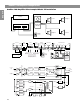
AmPlusTM 100 Amplifier Configurations English AmPlus 100 Amplifier With Two 70/100V Zones Installation Source Zone 1 Remote Volume Control AmPlus™ 100 Zone 2 Remote Volume Control Accessory 70/100V Transformer INPUTS A INPUT MODE LEVEL Ch1 Ch2 Zone 2 Ch1 Ch2 -6 2Ch -10 dual mono mono -6 - + REMOTE VOLUME -6 -10 ZONE 1 LINE OUTPUT ZONE 2 ZONE 1 POWER AMPLIFIER ZONE 2 70/100V -10 -40 dB 0 -40 dB 0 -40 dB 0 + BASS LEVEL Ch1 Ch2 ZONE 1 4-16 Ω ZONE 2 4-16 Ω XFR CT MODE OFF +10
AmPlusTM 100 Amplifier Specifications Power output Input sensitivity 315mV required to drive both channels to full power in any mode Input attenuation 0dB to off Input/Output configurations 1. 2-channel (stereo) 2. Mono into 4Ω load 3. Mono into 70/100V load 4. Dual-Mono (1 source/2 zones) 5. 2-channel (70/100V and 4Ω/Ch2) Input impedance 32kΩ balanced 11kΩ unbalanced Line output impedance 600Ω Line output distortion ≤0.
All About The AmPlusTM 50 Amplifier English AmPlus 50 amplifier controls Figure 5 INPUTS A LEVEL BASS GAIN REMOTE VOLUME POWER AMPLIFIER Ch1 Ch2 AmPlus 50 amplifier controls Ch1 -6 Ch2 -10 -6 70/100V -40 dB 0 -40 dB 0 + - + 4-16 Ω MODE -10 OFF +10 - + - + - 70/100V 4-16 Ω Inputs – The AmPlus 50 amplifier comes with two balanced inputs. They can be left and right from a stereo source; two mono sources can also be mixed.
AmPlusTM 50 Amplifier Configuration AmPlus 50 Amplifier Simple Monophonic Installation English Source AmPlus™ 50 Remote Volume Control INPUTS A Ch1 LEVEL -6 Ch2 -10 BASS GAIN REMOTE VOLUME POWER AMPLIFIER -6 70/100V 4-16 Ω MODE -10 -40 dB 0 -40 dB 0 OFF +10 Ch1 Ch2 + - Source + - + Internal Switch Settings: High Pass Filter: OFF - 70/100V 4-16 Ω Tap settings: less than or equal to 50W Remote Volume Control L R - + Ch.
AmPlus™ 50 Amplifier Specifications Power output English 70V mono: 50W into 98Ω 100V mono: 50W into 196Ω 4Ω mode: 70W into 4Ω Input sensitivity 315mV required to drive both channels to full power in any mode Input attenuation 0dB to -∞ Input/Output configurations 1. Mono into 4Ω load 2. Mono into 70/100V load 3. As an extension to the AmPlus 100 amplifier Input impedance 32kΩ balanced 11kΩ unbalanced Line output impedance 600Ω Line output distortion ≤0.
Bose® Corporation USA Canada Bose Ltd., 1-35 East Beaver Creek Road Richmond Hill, Ontario L4B 1B3 1-800-444-BOSE (1-800-444-2673) Phone hours – ET (eastern time): Weekdays 9 a.m. to 5 p.m. ET European Office Bose B.V., Nijverheidstraat 8 1135 GE Edam, Nederland TEL 0299-390139 FAX 0299-390109 Australia Bose Australia, Inc., 1 Sorrell Street Parramatta, N.S.W. 2150 TEL 02 204-6111 FAX 02 204-6122 Belgique/België Bose N.V.
©1998 Bose Corporation, The Mountain, Framingham, MA 01701-9168 USA JN97810 English