ESP-880 ESP-1240 ESP-4120 ControlSpace ® Engineered Sound Processors Installation Guide
pro.Bose.com Contents Introduction.......................................................................................... 12 Online Resources.................................................................................................................................... 12 Product Features..................................................................................................................................... 12 Available Accessories........................................................
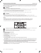
Important Safety Information pro.Bose.com Thank you for selecting Bose® ControlSpace ESP processors for your sound reinforcement system. This document is intended to provide professional installers with basic installation and safety guidelines for Bose® ControlSpace ESP processors in typical fixed-installation systems. Please read this document before attempting installation. WARNINGS: • This product is intended for installation by professional installers only.
pro.Bose.com Important Safety Information 12. Use only with the cart, stand, tripod, bracket, or table specified by the manufacturer or sold with the apparatus. When a cart is used, use caution when moving the cart/apparatus combination to avoid injury from tip-over. 13. Unplug this apparatus during lightning storms or when unused for long periods of time to prevent damage to this product. 14. Refer all servicing to qualified service personnel.
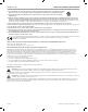
Installation and Operating Guide pro.Bose.com Introduction Thank you for choosing the Bose® ControlSpace® ESP-880/1240/4120 engineered sound processors. Bose ControlSpace ESP-880, ESP-1240, and ESP-4120 engineered sound processors are single-rack-space DSPs, available in analog I/O configurations of 8 x 8, 12 x 4, and 4 x 12. These cost-effective models meet today’s strict requirements for low latency audio processing with high-quality digital conversion and powerful DSP.
Installation and Operating Guide pro.Bose.com Available Accessories Accessory Cards ControlSpace® ESP-880/1240/4120 processors offer a rear panel digital expansion slot for adding network audio and control capabilities beyond what is available using the front panel RJ-45 connector. For systems requiring control network connections to be located on the rear panel (without streaming audio), the ControlSpace Network Control card is recommended for use. Figure 1.
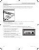
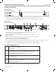
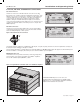
Installation and Operating Guide pro.Bose.com Product Overview Front Panel 2 1 Figure 3. Front Panel View 1. LED Indicators: Power, Signal, Ethernet and Serial indication. (See “Front Panel LED Indicators” below.) 2. Ethernet Connector: RJ-45 jack for front panel network connectivity. (See “Network Connections” on page 19.) Rear Panel Figure 4. Rear Panel View 1 2 3 9 5 4 8 6 7 1. Analog audio connectors: Mic/line-level balanced input and line-level output connectors.
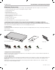
Installation and Operating Guide pro.Bose.com Hardware Installation Use the following procedure when setting up a ControlSpace® ESP-880/1240/4120 engineered sound processor for the first time. 1. Download and install the latest version of ControlSpace® Designer™ software 2. Unbox the ESP processor 3. Install option card 4. Rack-mount the ESP processor 5. Make analog audio I/O connections 6. Make CC-16, RS-232, and ESPLink connections 7. Connect GPIO devices 8. Establish a network connection 9.
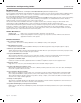
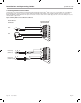
Installation and Operating Guide pro.Bose.com 5. Analog Audio Connections The ESP processor includes balanced dual-channel (6-terminal) Phoenix Contact® audio connectors. To help with ease of installation, the termination end of each connector includes printed terminal block descriptions. The following diagram shows recommended balanced/unbalanced wiring between the processor audio connectors and common audio plugs used to connect the ESP processor to external audio components. Figure 6.
Installation and Operating Guide pro.Bose.com 6. CC-16, RS-232, and ESPLink connections CC-16 Connector The CC-16 connector is an RS-485 network connection for use with Bose CC-16 zone controllers. Using the supplied Phoenix Contact® 3-pin labeled connector, up to 15 CC-16 zone controllers can be networked to control the ESP processor or any device on the Bose® ControlSpace® control network. An external power supply is required.
Installation and Operating Guide pro.Bose.com 7. Connect GPIO devices General Purpose Inputs/Outpus (GPIO) Five control inputs (GPI) and five controls outputs (GPO) are available and can be used to interface the ESP processor with external control hardware. General Purpose Inputs General-purpose control input ports are used to connect external hardware such as potentiometers (to control levels or gains) and switches (to invoke parameter sets).
pro.Bose.com Installation and Operating Guide 8. Network Connections ESP-880/1240/4120 processors feature two network connection methods: 1. A front-panel RJ-45 network port (See figure 9.) 2. Optional rear-panel network cards (See figure 10.) The front-panel connection is intended for localized configuration and monitoring. When used with a rear-panel network card, the frontpanel RJ-45 connector can serve as a convenient passthrough to the network connection on the rear panel.
Installation and Operating Guide pro.Bose.com Maintenance Operations Firmware / Software Upgrades ControlSpace® Designer™ software is updated on a periodic basis. Please check our website at pro.Bose.com for new software releases. Battery Replacement Single-rack ESP processors contain a replaceable lithium battery for maintaining the real time clock (RTC) capability of the system. These batteries last at least 10 years from time of production and usually do not require replacement.
Appendix pro.Bose.com Appendix Technical Specifications Integrated DSP ESP-880, ESP-1240, ESP-4120 Signal Processor 32-bit fixed/floating-point DSP + ARM, 456 MHz Maximum Calculation Delay Audio Latency 3.6 GIPS / 2.7 GFLOPS 43 s 860 μs (analog in to analog out) A/D and D/A Converters 24-bit Sample Rate 48 kHz Audio Performance Specifications Frequency Response THD+N Channel Separation (Crosstalk) Dynamic Range 20 Hz - 20 kHz (+0.3 dB/-0.1 dB) 0.
Additional Resources pro.Bose.com Technical Specifications Audio Inputs ESP-880 ESP-1240 ESP-4120 Input Channels 8 analog (balanced, mic/line level), 16 digital (via option card) 12 analog (balanced, mic/line level), 16 digital (via optional card) 4 analog (balanced, mic/line level), 16 digital (via optional card) Connectors, Input 3.81 mm Phoenix Contact®, 6-pin 3.81 mm Phoenix Contact®, 6-pin 3.
Additional Resources pro.Bose.com Additional Resources Visit us on the web at pro.Bose.com for more information, including specifications, technical literature, product warranty, parts and accessories, and global support contact information.
© 2013 Bose Corporation. All rights reserved. The Mountain, Framingham, MA 01701-9168 USA www.pro.Bose.com All trademarks are the property of their respective owners. AM372643 Rev.