Bose® FreeSpace® DS 100SE Loudspeaker Installation Guide* Installationsvejledning* Installationsanleitung* Guía de instalación* Guide d’installation* Guida all’installazione* Installatiehandleiding* Installationsanvisning* * For use by trained installers only. * Kun til brug for erfarne installatører. * Montage ausschließlich durch ausgebildetes Installationspersonal. * Para uso exclusivo de instaladores capacitados. * Réservé aux installateurs ayant suivi une formation.
FreeSpace® DS 100SE Loudspeaker P2 Phillips head fasteners (2) Bose ® FreeSp ace ® DS 100 SE Lou dsp eaker * For * Kun use by * Mont til brug trained * Para age aussfor erfarinstallers * Rése uso exclu chlie ne insta only. * Solo rvé aux sivo ßlich durc llatører. de insta h ausg * Uitslu per l’uso installateu lador ebild itend * Ska da es capa etes voor parte rs ayan enda st anvä gebruik di insta t suivi une citad Installatio nspe ndas door llator form os. rsona av utbild ervar i profe ation l.
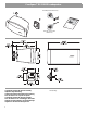
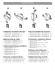
Installation Requirements Installation Installation • Choose a mounting position, method, and hardware consistent with local building codes and regulations. • Pour le montage, choisissez une position, une méthode et des composants conformes aux codes et réglementations en vigueur. • Due to various construction methods and materials used today, the hardware for securing the loudspeaker to the mounting surface is not supplied.
Installation Options Mounting and junction box options 1. Direct mount (in-wall or on-wall wiring) Montage et options de la boîte de branchement 2. Bose® On-Wall Junction Box (accessory) 1. Montage direct (câblage encastré ou apparent) 3. Bose® In-Wall Junction Box (accessory) 4. Standard steel 4" x 4" junction box (U.S. only) 5. Standard steel 4" x 4" junction box (U.S. only) Indstillinger til montering og samlingsboks 2. Boîte de jonction pour montage mural en surface Bose® (accessoire) 3.
Installation Options Loudspeaker orientation and angle Angle et orientation des enceintes 1. 2. 3. 4. 1. 2. 3. 4.
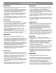
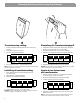
Removing End Cap and Accessing Tap Settings Transformer tap setting Einstellung für Transformatorabgriff 1. Position loudspeaker vertically with endcap closest to logo facing up. 2. Pull forward on endcap to remove. 3. Set tap by turning the thumbwheel. 70V 1. Positionieren Sie die Lautsprecher vertikal, wobei die Blende, die dem Logo am nächsten ist, nach oben weist. 2. Ziehen Sie die Blende nach vorn, um sie zu entfernen. 3. Stellen Sie den Abgriff durch Drehen der Einstellscheibe ein. 70V 12.
Removing End Cap and Accessing Tap Settings Puissance du transformateur Aftappen bij de transformator 1. Positionner l’enceinte verticalement, en orientant vers le haut le couvercle d’extrémité proche du logo. 2. Déposer le couvercle d’extrémité en tirant. 3. Tourner la molette pour régler la puissance. 70V 1. Plaats de luidsprekerbox verticaal met het afdekplaatje dat het dichtst bij het logo zit naar boven. 2. Trek het afdekplaatje naar voren om dit te verwijderen. 3.
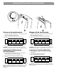
Preparing the Loudspeaker Before Mounting Vertically Twiddler® array adjustment Twiddler®-Array-Einstellung To maintain 180° horizontal dispersion when the loudspeaker is mounted vertically: So erhalten Sie den horizontalen 180°-Abstrahlungsbereich bei vertikaler Montage: 1. 2. 3. 4. 5. 6. 1. 2. 3. 4. 5. 6. Remove endcaps and grille. Remove screws from array. Rotate array. Reinsert screws. Rotate loudspeaker. Reattach grille and endcaps. Entfernen Sie die Blenden und das Gitter.
Preparing the Loudspeaker Before Mounting Vertically Réglages de l’ensemble Twiddler® Twiddler®-luidsprekers bijstellen Pour préserver une dispersion horizontale sur 180° lorsque l’enceinte est montée verticalement Voor een horizontale dispersie van 180° als de luidsprekerbox verticaal is bevestigd: 1. 2. 3. 4. 5. 6. 1. 2. 3. 4. 5. 6. Déposer les couvercles d’extrémité et la grille. Déposer les vis du groupe de haut-parleurs. Faire tourner le groupe de haut-parleurs: Réinsérer les vis.
Preparing the Loudspeaker Before Mounting Vertically Rotating logo Rotation du logo For vertical mounting: Pour le montage vertical : 1. Firmly grasp logo and pull away from grille. 2. Rotate logo and release. 1. Saisissez fermement le logo et tirez pour l’écarter de la grille. 2. Faites tourner le logo et relâchez-le. Roterende logo Rotazione del logo Til lodret montering: Per il montaggio in posizione verticale: 1. Tag godt fat om logo, og træk det væk fra gitteret. 2. Drej logo, og slip. 1.
Preparing the Loudspeaker for Desired Adjustment Rotating loudspeaker arm Rotation du bras de haut-parleur For horizontal mounting with yaw adjustment or vertical mounting with pitch adjustment: Pour montage horizontal avec réglage de l’inclinaison latérale ou montage vertical avec réglage de l’inclinaison verticale : 1. Remove screws from loudspeaker arm. 2. Rotate arm. 3. Reinsert screws from loudspeaker arm. 1. Enlever les vis du bras du haut-parleur. 2. Faites pivoter le bras. 3.
Wiring the Bracket 12
Wiring the Bracket Wire gauge requirements From loudspeaker line wiring to bracket Use 18 AWG (0.8 mm2) to 14 AWG (2.0 mm2) size wire only. Krav til ledningens tykkelse Fra højttalers tilslutning til beslag Brug kun 18 AWG (0,8 mm2) til 14 AWG (2,0 mm2)-kabler. Kabelquerschnittanforderungen Von der Lautsprecherverkabelung zur Halterung Verwenden Sie nur ein 18-20 AWG-Kabel (mit 0,8 bis 2,0 mm2 Querschnitt.
Wiring the Bracket Ceramic terminal and thermal switch To meet combination systems specifications required in some regions of Europe (see page 30) The ceramic block, thermal switch (fuse), and wires included with the Bose® In-Wall and On-Wall Junction Boxes provide an installation method that ensures that if an individual loudspeaker fails, it will not cause a short circuit that would result in the failure of the rest of the loudspeakers on the same line.
Wiring the Bracket Wire gauge requirements Diamètre des câbles From bracket to ceramic block Use thermal switch (fuse) and wires included with the Bose® junction boxes. Du support au bornier céramique Utiliser le fusible thermique et les câbles fournis avec les boîtes de jonction Bose® . From loudspeaker line wiring to ceramic block Use 18 AWG (0.8 mm2) to 14 AWG (2.0 mm2) size wire only. Du point de câblage de l’enceinte au bornier céramique Utiliser uniquement des câbles de 0,8 mm2) à 2,0 mm2.
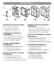
Mounting the Bracket Direct mount with in-wall wiring • Use M4 or #8 screws with appropriate anchors. • At least two (2) screws must be used to hold the wall mount bracket to the support structure (stud). • Do not overtighten screws. If using a power drill, set to a low torque setting. Direkte montering med ledninger i væggen • Brug M4- eller nr. 8-skruer med egnede ankre. • Mindst to (2) skruer skal bruges til at holde på vægmonteringens beslag til den understøttende struktur (stolpe).
Mounting the Bracket Preparing the wire for direct mount with on-wall wiring Préparation du câble pour montage direct avec câblage sur le mur Trim back the outer jacket (A) and some of the wire insulation (B) to expose enough bare wire (C) to attach to the terminals. Dénuder la gaine externe (A) et une partie plus courte de l’isolant des fils (B) afin d’exposer la longueur de fil nu (C) nécessaire au branchement.
Mounting the Bracket Direct mount with on-wall wiring 1. Remove bracket door(s). 2. Center wires over strain relief clamp hole and insert strain relief clamp: • Make sure the wires are seated in the strain relief clamp wire channels. • Make sure the wires are protected by their outer jacket at the point where the strain relief clamp is applied. 3. Tighten strain relief clamp. 4. Attach bracket to wall: • Use M4 or #8 screws with appropriate anchors.
Mounting the Bracket Montage direct avec câbles sur le mur Rechtstreeks monteren met bedrading op de wand 1. Déposer le couvercle du support. 2. Centrer les câbles au-dessus de l’orifice de la languette antitraction et insérer celle-ci : • Les câbles doivent être correctement insérés dans les canaux de la languette anti-traction. 1. Verwijder de klep(pen) van de beugel. 2.
Mounting the Bracket With Bose On-Wall Junction Box 1. Attach junction box to wall: • Use M4 or #8 screws with appropriate anchors. • At least two (2) screws must be used to hold the wall mount bracket to the support structure (stud). • Do not overtighten screws. If using a power drill, set to a low torque setting. 2. Attach bracket to junction box using screws provided (A) with junction box.
Mounting the Bracket Avec boîtier Bose® de branchement sur le mur 1. Fixer la boîte de jonction au mur : • Utiliser des vis M4 ou n° 8 avec les chevilles appropriées. • Utiliser au moins deux (2) vis pour fixer le support de montage mural à la structure de fixation. • Ne pas serrer excessivement les vis. Régler la visseuse électrique avec un faible couple. 2. Fixer le support à la boîte de jonction à l’aide des vis (A) fournies avec celle-ci.
Mounting the Bracket With Bose® In-Wall Junction Box Mit Bose® Unterputz-Verbindungsdose 1. Use cutting template and instructions included with the Bose In-Wall Junction Box. 2. Cut hole. 3. Insert junction box. 4. Tighten junction box anchors. 5. Attach bracket to junction box: • Use M4 or #8 screws. 1. Verwenden Sie die Schnittschablone und die Anweisungen, die Sie mit der Bose Unterputz-Verbindungsdose erhalten haben. 2. Schneiden Sie ein Loch. 3. Setzen Sie die Verbindungsdose ein. 4.
Mounting the Bracket Avec boîtier Bose® de branchement dans le mur 1. Utiliser le gabarit et le feuillet d’instructions fournis avec la boîte de jonction pour montage mural encastré Bose. 2. Découper l’orifice d’insertion. 3. Insérer la boîte de jonction. 4. Serrer les vis d’ancrage de la boîte de jonction. 5. Fixer le support au mur : • Utiliser des vis M4 ou n° 8. • 1. Gebruik de sjabloon en de handleiding die u bij de Boseinbouwkabeldoos hebt ontvangen. 2. Maak de opening. 3.
Mounting the Bracket US-ONLY • KUN USA • NUR USA • SÓLO EE UU • ÉTATS-UNIS UNIQUEMENT • SOLO USA • ALLEEN VS • ENDAST USA With standard steel 4" x 4" junction box The FreeSpace® DS 100SE loudspeaker can be mounted directly on standard U.S. steel 4" x 4" junction boxes. There may be several junction boxes available that are compatible with the FreeSpace DS 100SE wall mount bracket, but Bose Corporation only recommends the junction boxes it has validated. U.S.
Mounting the Bracket US-ONLY • KUN USA • NUR USA • SÓLO EE UU • ÉTATS-UNIS UNIQUEMENT • SOLO USA • ALLEEN VS • ENDAST USA Bose DS Trim Plate (accessory) With standard steel 4" x 4" junction box The FreeSpace® DS 100SE loudspeaker can be mounted directly on standard U.S. steel 4" x 4" junction boxes. There may be several junction boxes available that are compatible with the FreeSpace DS 100SE wall mount bracket, but Bose Corporation only recommends the junction boxes it has validated. U.S.
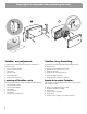
Mounting the Loudspeaker to the Bracket Positioning and securing the loudspeaker Positionieren und Sichern des Lautsprechers 1. Align the holes of the loudspeaker arm and bracket. 2. Insert, but DO NOT TIGHTEN, the fastener: 1. Richten Sie die Löcher am Lautsprecherarm und an der Halterung aus. 2. Setzen Sie das Befestigungswerkzeug ein, aber ziehen Sie es nicht fest: P2 Phillips head Theft-deterrent 3mm pin-in-hex head 3. Adjust the loudspeaker to the desired angle. 4.
Mounting the Loudspeaker to the Bracket Positionnement et sécurisation du haut-parleur De luidsprekerbox plaatsen en bevestigen 1. Aligner les trous du montant de l’enceinte et du support. 2. Insérer l’axe à visser SANS LE SERRER : 1. Lijn de openingen in de luidsprekerarm uit met openingen in de beugel. 2. Steek de bevestigingsschroef in de openingen maar DRAAI DEZE NIET AAN: Tête cruciforme Phillips P2 Tête hexagonale antivol 3 mm 3. Ajuster l’enceinte à l’angle voulu. 4.
Connecting the Loudspeaker Wire to the Bracket Plug the wire into the bracket 1. Remove paint shield (if not already removed). 2. Snap on loudspeaker wire plug to bracket connector. 3. Insert and tighten screw on plug. Sæt den anden ende af kablet ind beslag Insérez l’autre extrémité du câble dans le support 1. Déposer la pellicule de protection contre la peinture si ce n’est déjà fait. 2. Enclencher la prise du câble d’enceite sur le connecteur du support. 3. Insérer la vis de la fiche et la serrer. 1.
Other Considerations Uso de la pieza de ajuste del cable de seguridad • Algunos códigos de construcción regionales requieren el uso de un método secundario para fijar los altavoces a estructuras de apoyo con el fin de obtener seguridad adicional. • Seleccione una posición, un método y accesorios de montaje que respeten los códigos y normas de construcción locales. • Puede conectar un cable de seguridad al altavoz FreeSpace® DS 100SE utilizando la pieza de ajuste roscada de la parte posterior de la caja.
Safety and Regulatory Compliance The DS 100SE has passed extensive testing and complies with the following specifications and uses: LISTED to ANSI/UL 1480-2005 • Fire Protective Signaling Use – UL Category UUMW, File Number S 3241. Control Number 42S9 when installed with a junction box (on-wall or in-wall). Not for use with DC-supervised systems. • General Purpose Use – UL Category UEAY, File Number S 5591 Control Number 3N89. • Suitable for use outdoors in wet locations.
©2008 Bose Corporation, The Mountain Framingham, MA 01701-9168 USA AM300289 Rev.