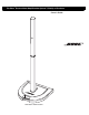
The Bose® Personalized Amplification System™ Family of Products Owner’s Guide www.bose.
Safety Information WARNING: To reduce the risk of fire or electrical shock, do not expose the system to rain or moisture. CAUTION: To prevent electric shock, match the wide blade of the line cord plug to the wide slot of the AC (mains) receptacle. CA AUTION UTION AVI VI S RISK OF ELECTRICAL SHOCK DO NOT OPEN RISQUE DE CHOC ÉLECTRIQUE NE PAS OUVRIR CAUTION: TO REDUCE THE RISK OF ELECTRIC SHOCK, DO NOT REMOVE COVER (OR BACK). NO USER-SERVICABLE PARTS INSIDE. REFER SERVICING TO QUALIFIED PERSONNEL.
Important Safety Instructions 1. Read these instructions. 2. Keep these instructions. 3. Heed all warnings. 4. Follow all instructions. 5. Do not use this apparatus near water. 6. Clean only with a dry cloth. 7. Do not block any ventilation openings. Install in accordance with the manufacturer’s instructions. 8. Do not install near any heat sources, such as radiators, heat registers, stoves or other apparatus (including amplifiers) that produce heat. 9.
Important Safety Instructions 19. Avoid Power Lines – Use extreme care when installing an outside antenna system to keep from touching power lines or circuits, as contact with them may be fatal. Do not install external antennas near overhead power lines or other electric light or power circuits, nor where an antenna can fall into such circuits or power lines. 20.
Contents Where to find... Setup . . . . . . . . . . . . . . . . . . . . . . . . . . . . . . . . . . . . . . . . . . . . . . . . . . . . . . . . . . . . . . . . . . . . . . . . Before you begin . . . . . . . . . . . . . . . . . . . . . . . . . . . . . . . . . . . . . . . . . . . . . . . . . . . . . . . . . . . Unpacking . . . . . . . . . . . . . . . . . . . . . . . . . . . . . . . . . . . . . . . . . . . . . . . . . . . . . . . . . . . . . . . .
Setup Before you begin Thank you for purchasing one of the Bose® Personalized Amplification System™ family of products. This new revolutionary technology brings the benefits of the intimate acoustic concert to amplified performances. Benefits for musicians • You control the sound - Just as in an unamplified performance, you, and no one else, control the sound. You will no longer wonder how you sound to your fellow musicians or to your audience.
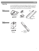
Setup Unpacking Your Personalized Amplification System™ product (Figure 1) is delivered to you in two cartons. One carton contains the power stand, power stand AC line cord, remote control, and remote control cable. The other carton contains the Cylindrical Radiator™ loudspeaker. If you purchased the optional Model B1 bass module or the carrying bag for the Model L1 Cylindrical Radiator loudspeaker (Figure 2), they are packaged separately.
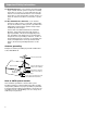
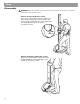
Setup Placing the product in the right location for your performance Before you start to assemble this product, it is a good idea to find the best location for it. CAUTION: The completed unit weighs about 60 lb. Moving the completely assembed unit is not recommended. Placing the power stand in the right location is an important step in the process of setting up this product to create your own individualized sound.
Setup Product assembly 1. Place the power stand on the floor. Place it on a flat, dry, stable surface at the rearmost part of the stage, handle facing forward, behind the performer. 4. Connect the remote control to the power stand. Plug the remote control cable into either end of the remote. Plug the other end into the Remote jack. CAUTION: The completed unit weighs about 60 lb. Moving the completely assembed unit is not recommended.
Setup Disassembly CAUTION: Before disassembly, turn the power off and then remove the AC power cord and all other cables from the power stand. Remove the top loudspeaker section Place one foot on the power stand to support your back. Firmly grasp the top section with one hand. Using your other hand, press the release button with your thumb and remove the top section from bottom section.
Setup Connecting a bass module to the power stand (optional) The Bass/Amp 3 OUT jack on the power stand can adequately drive one or two Model B1 bass modules. Bass modules can be placed on the floor vertically or horizontally. Up to four modules may be stacked when placed horizontally (Figure 4). CAUTION: Do not connect more than two Model B1 bass modules to the Bass/Amp 3 OUT connector on the power stand.
Setup Connecting two bass modules Connect the first bass module to the power stand as shown in “Connecting one bass module” on page 11. Insert one end of the second bass module cable into the unused jack on the rear panel of the first bass module. Insert the other end of the cable into one of the jacks on the rear panel of the second bass module. CAUTION: Do not connect more than two Model B1 bass modules to the Bass/Amp 3 OUT connector on the power stand.
Setup Setting up additional power stands for more bass output If you need more bass output than a single power stand with two bass modules can deliver, there is a solution. You can purchase an additional power stand (without loudspeakers) and use its three amplifier channels to drive up to six more bass modules. The second power stand operates as a slave to your primary power stand.
Setup Distributed bass setup A distributed bass configuration (Figure 8) can be created by using each of the three power stand amplifiers individually to drive additional bass modules for different performers. For example, let’s say you are a member of an ensemble that includes bass guitar, drums, and a keyboard and all members have a full (optional bass module included) Personalized Amplification System™ unit. When the ensemble plays in louder clubs or larger performance spaces, a bigger sound is needed.
Setup Shared bass setup In a shared bass configuration (Figure 9), the musicians can use all the available bass power. Based on the previous example, a shared bass configuration could be set up for the bass player and the drummer. This involves inputting the drums and bass to the master power stand on channels 1 and 2 and driving a full base configuration with a second power stand.
Controls, Indicators, and Connections Channel 1/2 connections and controls Unbal Unbal Input ..........................................Combination XLR (mic) or ¼-inch TRS (Line) input jack. Inserting a male XLR connector sends the input signal to a balanced microphone preamplifier. Inserting a ¼-inch phone connector sends the input signal to an unbalanced highimpedance line-level circuit which is suitable for most instruments such as active or passive guitars or basses, keyboards, etc.
Controls, Indicators and Connections Power amp patch, bass, remote and AC power connections TRS Bal/Unbal ® Commercial Audio Product 917D Used only when a Cylindrical Radiator™ loudspeaker is NOT installed in the power stand. Amp 1 IN....................................Amplifier 1 input jack. Amp 2 IN....................................Amplifier 2 input jack. Amp 3 IN....................................Amplifier 3 input jack. All Amps IN ...............................Input jack to all amplifiers.
Controls, Indicators and Connections Remote control features CH 1 CH 2 0 -12 +12 0 -12 -12 +12 0 MID -12 +12 0 -12 0 HIGH 0 LOW +12 +12 -12 +12 LEVEL SIG / OL 0 SIG / OL 0 12 12 MASTER 0 12 CH1/CH2 HIGH -12 to +12 ...............Cuts (-) or boosts (+) high-frequency sounds. CH1/CH2 MID -12 to +12 .................Cuts (-) or boosts (+) mid-frequency sounds. CH1/CH2 LOW -12 to +12 ................Cuts (-) or boosts (+) low-frequency sounds. CH1/CH2 LEVEL 0 to 12..............
Operating Instructions Producing individualized sound This product will produce sound whether it is properly adjusted or not. However, if you take a few moments to follow a simple startup procedure, you can optimize the sound for a superior presentation based on your performance style and preferences. Unless you make big changes in how you perform, this is typically a one-time event. 1. Set all gain and level controls on the power stand and remote to zero (0). 2. Set the Power switch to On.
Operating Instructions Using an effects processor Note: Connecting an effects unit requires a cable with a ¼-inch phone plug on each end. 1. Insert the phone plug on one end of your cable half way into the Channel 1 Insert jack. 2. Plug the other end of the cable into your effects unit. 3. Plug the cord coming out of the effects unit into the Channel 3 Line IN jack. 4. Adjust Channel 3 Level for the amount of effect added to Channel 1.
Maintaining Your Product Troubleshooting If you experience problems while using this product, try the following solutions. If you still can’t solve the problem, contact your Bose® dealer or Bose Customer Service to arrange for service. Recommended troubleshooting tools: • Portable voltmeter • Cable tester • XLR and ¼-inch phone plug cables • 4-wire bass module cable • Spare T15AH fuses • Spare AC power cord Problem What to do System is plugged in, power switch is on, but power LED is off.
Maintaining Your Product Problem What to do When using the Insert jack as a send to an effects unit, you hear only effect and no dry signal. • Make sure the ¼-inch plug is inserted only half way into the jack (first click). When the plug is inserted all the way, it breaks the signal to the power amp and sends all of the signal to the effects unit. The remote is not working. • Make sure the remote cable connector is firmly seated into the jack on the remote and the power stand.
Technical Information Mechanical Dimensions • Power stand: 26.0 in (660 mm) W x 26.0 in (660 mm) D x 5.0 in (127 mm) H • Cylindrical Radiator™ loudspeaker (each section): 3.5 in (89 mm) W x 4.0 in (105 mm) D x 43.0 in (1092 mm) H • Remote control: 2.8 in (71 mm) W x 5.6 in (141 mm) D x 1.6 in (40 mm) H • Bass module (optional): 10.3 in (250 mm) W x 18.0 in (457 mm) D x 15.3 in (380 mm) H Weight • Power stand: 35 lb (16 kg) • Lower line array: 16.0 lb (7 kg) • Upper line array: 14.
©2003 Bose Corporation, The Mountain, Framingham, MA 01701-9168 USA 263976 AM Rev.00 JN30987 www.bose.