PowerMatch™ PM8500 Configurable Professional Amplifier PowerMatch™ PM8500N Configurable Professional Amplifier PM8500 / PM8500N PowerMatch ™ Configurable Professional Power Amplifier User Guide
This Page intentionally blank
pro.Bose.com Contents Introduction..................................................................................................................................................... 12 Additional Documents................................................................................................................................. 12 Product Features...........................................................................................................................................
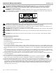
Important Safety Information pro.Bose.com This product is intended for installation by professional installers only! Thank you for selecting Bose® PowerMatch™ amplifiers for your sound reinforcement system. This document is intended to provide professional installers with basic installation and safety guidelines for Bose PowerMatch amplifiers in typical fixed-installation systems. Please read this document before attempting installation.
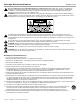
pro.Bose.com Important Safety Information 15. To prevent risk of fire or electric shock, avoid overloading wall outlets, extension cords, or integral convenience receptacles. 16. Do not let objects or liquids enter the product – as they may touch dangerous voltage points or short-out parts that could result in a fire or electric shock. 17. See product enclosure for safety-related markings. 18. No naked flame sources, such as lighted candles, should be placed on the apparatus. 19.
Información de seguridad importante pro.Bose.com Sólo un instalador profesional deberá montar este producto. Gracias por seleccionar los amplificadores Bose® PowerMatch™ para su sistema de refuerzo de sonido. Este documento ofrece a los instaladores profesionales instrucciones básicas de instalación y seguridad para los amplificadores Bose PowerMatch™ en sistemas típicos de instalación fija. Lea este documento antes de intentar la instalación. ADVERTENCIA: No exponga este aparato a salpicaduras o goteo.
pro.Bose.com Información de seguridad importante 15. Para prevenir el riesgo de incendio o descargas eléctricas, evite sobrecargar los enchufes, alargadores o receptáculos de las tomas. 16. Evite que caigan objetos o líquidos sobre el producto, ya que podrían entrar en contacto con puntos de niveles de voltaje altos o partes que podrían sufrir un cortocircuito y causar incendios o descargas eléctricas. 17. Consulte las indicaciones de seguridad en la caja del producto. 18.
Informations importantes pour la sécurité pro.Bose.com L’installation de ce produit est réservée à un technicien professionnel ! Merci d’avoir choisi des amplificateurs professionnels Bose® PowerMatch™ pour votre système d’amplification du son. Ce document à l’intention des installateurs professionnels contient les directives de pose et de sécurité relatives aux amplificateurs professionnels Bose PowerMatch™ en installation fixe. Lisez attentivement ce document avant l’installation.
pro.Bose.com Informations importantes pour la sécurité 15. Pour éviter tout risque d’incendie ou d’électrocution, ne surchargez pas les prises murales, les rallonges ou les prises multiples. 16. Ne laissez jamais de l’eau ou des objets pénétrer à l’intérieur du produit : des éléments sous tension pourraient être touchés, et un court-circuit risquerait de provoquer un incendie ou une électrocution. 17. Consultez les marquages de sécurité sous le boîtier du produit. 18.
Wichtige Sicherheitshinweise pro.Bose.com Dieses Produkt darf nur von fachkundigen Monteuren installiert werden! Vielen Dank, dass Sie Bose® PowerMatch™Verstärker für Ihr Klangverstärkungssystem gewählt haben. Dieses Dokument soll fachkundigen Monteuren grundlegende Installations- und Sicherheitsrichtlinie für Bose PowerMatch™-Verstärker in typischen Festinstallationssystemen bieten. Bitte lesen Sie dieses Dokument vor der Installation durch.
pro.Bose.com Wichtige Sicherheitshinweise 14. Wenden Sie sich bei allen Reparatur- und Wartungsarbeiten nur an qualifiziertes Kundendienstpersonal. Wartungsarbeiten sind in folgenden Fällen nötig: Bei jeglichen Beschädigungen wie z. B.
User Guide pro.Bose.com Introduction Thank you for choosing the Bose® PowerMatch™ PM8500 configurable professional power amplifier! The PowerMatch PM8500 Configurable Professional Amplifier delivers concert sound quality for fixed-installation sound reinforcement systems.
User Guide pro.Bose.com PowerMatch™ Amplifier Product Line Overview PowerMatch PM8500 and PM8500N The PowerMatch PM8500 and PM8500N are configurable professional audio amplifiers. The two versions are identical except that the PM8500N version adds an RJ45 connector on the rear panel to allow network setup, control, and remote monitoring of multiple PM8500N units using Bose® ControlSpace® Designer™ software and standard network equipment.
User Guide pro.Bose.com Controls, Display, and Connectors Figures 2 and 3 detail the various elements found on the front and rear panels of the PM8500 and PM8500N amplifiers. Figure 2. PM8500 and PM8500N Front Panel View 2 1 6 8 3 5 7 8 4 1. LED Indicators 5. Menu Soft Keys (1-5) 2. LCD 6. USB connector 3. Navigation Soft Key 7. Front airflow vents 4. Rotary Encoder 8. Front rack-mount ears Figure 3. PM8500N Rear Panel View (PM8500 identical except no RJ-45 network connector) 12 18 9.
User Guide pro.Bose.com Hardware Installation Unpacking The product box includes the following items: Figure 4.
User Guide pro.Bose.com Making Connections Connection and Configuration Steps Use the following procedure when setting up the PM8500 for the first time. Subsequent sections in this guide give details on each step. 1. Install any accessory cards (optional) 2. Mount the amplifier into the rack 3. Connect power cable and retaining clip 4. Turn on amplifier 5. Enable Standby Mode 6. Configure amplifier (use front panel or ControlSpace® Designer™ software) 7. Wire input connection from source device(s) 8.
User Guide pro.Bose.com Wiring Input Connectors The balanced line-level analog inputs utilize 3-pin terminal block connectors (Phoenix Contact #1776168, supplied). For balanced inputs, strip the wire ¼ inch (6 mm) and connect the respective positive, negative, and ground terminals as indicated on the unit and in Figure 6. For unbalanced inputs, the connector should be wired with Pin 1 = positive, with Pin 2 and Pin 3 connected with a jumper wire (not supplied) and then connected to the input cable shield.
User Guide pro.Bose.
pro.Bose.com User Guide Figure 9. Output wiring showing mixed configuration Note: Changing the output configuration will automatically place the unit in Standby Mode to allow the safe installation of loudspeaker cable connections to the rear-panel output terminal blocks. Fault Notification Output The PM8500 features a hardware fault notification circuit. This circuit drives a normally open or normally closed contact closure (1A, 30 VDC maximum).
User Guide pro.Bose.com Setup and Configuration Figure 11 shows the basic signal flow and available DSP functions available to manipulate each individual input channel. Some functions and advanced parameters can only be modified using ControlSpace® Designer™ software. See “Function Table” on page 40 to view configurations required to access functions and features. Figure 11.
User Guide pro.Bose.com Control Panel Description Figure 12. PM8500 Front Panel 5 6 7 8 9 1 2 3 4 10 11 1 Fault LED Indicator LED lights red when a fault condition has been detected. For more information see Figure 21, “Fault Conditions” on page 38. 2 Clip LED Indicator Indicates red when the input signal reaches full scale. Bose recommends that you reduce input levels to prevent this condition.
User Guide pro.Bose.com Front Panel Control Menu Structure The displays and user controls accessible by the front panel are presented in the following menu structure illustration: Figure 13.
User Guide pro.Bose.com MAIN MENU OPERATING ➞ Mute All Main Menu Description The MAIN MENU offers five areas of control: • • • • • Available Controls Navigation Soft Key: Back to OPERATING display. • • • • • Notes Level Meter DSP Configuration Utility Menu Soft Key #1: Enters LEVEL menu. Menu Soft Key #2: Enters METER Menu. Menu Soft Key #1: Enters DSP Menu. Menu Soft Key #1: Enters CONFIG Menu. Menu Soft Key #1: Enters UTILITY Menu.
User Guide pro.Bose.com MAIN MENU < LEVEL < OUTPUT ATTEN LEVEL ➞ Output Mute Output Attenuate Input Mute Input Sensitivity Input Source Description This display allows you to attenuate each configured output channel. For channels set to output modes other than Mono, attenuation control is bound by the configured groupings. Two output channels are displayed at one time. Real-time output is displayed and affected by changing attenuation.
User Guide pro.Bose.com MAIN MENU < LEVEL < INPUT SOURCE LEVEL ➞ Output Mute Output Attenuate Input Mute Input Sensitivity Input Source Description This display allows you to select an analog or digital audio source for each input channel. No p arameters can be modified if the amplifier is without a digital input card. Available Controls To access Input Source, use the rotary encoder dial from the LEVEL menu to highlight, then press to select. Navigation Soft Key: Back to LEVEL menu.
User Guide pro.Bose.com MAIN MENU < METER < INPUT METER ➞ Output Voltage Input Meter Description This display allows you to monitor each input channel. You can also mute all input channels. Available Controls To access the Input Meter, use the rotary encoder dial from the METER menu to highlight, then press to select. Navigation Soft Key: Back to METER menu. Menu Soft Key #5: Enables/disables muting of all output channels. Options Mute ALL, Unmute ALL.
User Guide pro.Bose.com MAIN MENU < DSP < ARRAY EQ DSP ➞ Speaker Presets Array EQ Delay Limiting Description This display allows you to apply additional EQ to each input channel (A-H) that feeds signal to RoomMatch™ loudspeakers in array configurations. Available Controls To access Array EQ, use the rotary encoder dial from the DSP menu to highlight, then press to select. Navigation Soft Key: Back to DSP menu.
User Guide pro.Bose.com MAIN MENU < DSP < LIMITING DSP ➞ Speaker Presets Array EQ Delay Limiting Description This display allows you to adjust limiting parameters that allow for loudspeaker driver protection for each output channel. Available Controls To access Limiting, use the rotary encoder dial from the DSP menu to highlight, then press to select. Navigation Soft Key: Back to DSP menu.
User Guide pro.Bose.com MAIN MENU < CONFIGURE < CONFIG OUTPUTS ➞ CONFIG Output Config Input Routing Description This display allows you to configure the output section of the amplifier for various output modes. Available Controls To access Output Configuration, use the rotary encoder dial from the DSP menu to highlight, then press to select. Navigation Soft Key: Back to CONFIG menu. Menu Soft Key #5: Enables the selection of the output channel (or output groupings) using the rotary encoder dial.
User Guide pro.Bose.com MAIN MENU < UTILITY ➞ UTILITY Standby Mode Alarm Log Network Setup (Device ID) Lock Front Panel Set Front Panel Lock Combination Display Restore Factory Settings Firmware Version Description The UTILITY menu allows you to access additional configuration parameters of the amplifier. Available Controls Navigation Soft Key: Return back to MAIN MENU. Menu Soft Key #1-5: Changes menu to respective category.
User Guide pro.Bose.com MAIN MENU < UTILITY < ALARM LOG UTILITY ➞ Standby Mode Alarm Log Network Setup (Device ID) Lock Front Panel Set Front Panel Lock Combination Display Restore Factory Settings Firmware Version Description This display allows you to view, clear, and erase captured alarm notifications. Available Controls To access ALARM LOG, use the rotary encoder dial from the DSP menu to highlight, then press to select. Navigation Soft Key: Back to UTILITY menu.
User Guide pro.Bose.com MAIN MENU < UTILITY < Lock Front Panel UTILITY ➞ Standby Mode Alarm Log Network Setup (Device ID) Lock Front Panel Set Front Panel Lock Combination Display Restore Factory Settings Firmware Version Description This display allows you to view the current un-lock combination and ability to lock the front panel controls to prevent tampering. Available Controls To access Lock Front Panel, use the rotary encoder dial from the DSP menu to highlight, then press to select.
User Guide pro.Bose.com MAIN MENU < UTILITY < RESTORE FACTORY UTILITY ➞ Standby Mode Alarm Log Network Setup (Device ID) Lock Front Panel Set Front Panel Lock Combination Display Restore Factory Settings Firmware Version Description This display allows you to erase all settings and return the amplifier options to the state set by the factory. Available Controls To access the Restore Factory Settings menu, use the rotary encoder dial from the UTILITY menu to highlight, then press to select.
User Guide pro.Bose.com Sample Output Configurations for Different Loudspeaker Loads This table should help you select the appropriate output mode for a given loudspeaker load. Figure 14. Loudspeaker load output configurations 2Ω Power Rating (20 - 20 kHz) THD For Power Rating 4Ω 8Ω 70 V <0.
pro.Bose.com User Guide Configuration of RoomMatch™ Two-Module Array with a RoomMatch RMS215 Subwoofer Module (Example 2) In this example, two full-range RoomMatch array modules and one subwoofer module are connected to one PowerMatch amplifier, arranged as follows: (1) Bose® RoomMatch 7010 array module loudspeaker (70° H x 10° V) (1) Bose RoomMatch 9040 array module loudspeaker (90° H x 40° V) (2) Bose RoomMatch RMS215 subwoofer array modules.
User Guide pro.Bose.com Maintenance Operations Updating Firmware and Speaker EQ Presets The PM8500 amplifier contains two user-updatable files: Firmware and loudspeaker EQ files. These files can both be updated from ControlSpace® Designer™ software using a PC connected to either the USB connection on the front panel of the amplifier, or, in the case of the PM8500N model, an Ethernet network connection. Please refer to ControlSpace Designer software documentation on pro.Bose.
pro.Bose.com User Guide To update the amplifier’s EQ file, select System -> Update EQ File. Same as the process to update firmware, if a newer version is available from the drop-down list under “Latest Version,” select the update checkbox and click the Update button. Figure 19. EQ Update window Note: Between ControlSpace® Designer™ software releases, PowerMatch™ firmware updates and loudspeaker EQ files may be available.
User Guide pro.Bose.com About the Alarm Log and Fault Indicator The PowerMatch™ amplifier monitors operating temperature, power supply status, amplifier status, open and short wiring, and additional conditions for issues. When issues are detected, information is stored in the amplifier in an internal log found by accessing MAIN MENU < UTILITY < Alarm Log from the front panel. Information from the alarm log can also be viewed using ControlSpace® Designer™ software.
User Guide pro.Bose.com Troubleshooting Problem No power Power is on, but no sound Possible Solution • Turn on power switch. Clip, Limit, and Signal LEDs should stay lit for approximately the first 15 seconds, after which the amplifier should be fully ready for operation. The amplifier’s LCD screen will show the firmware version screen after about 10 seconds, then revert to the operating screen. • Check power cable, ensure retaining clip is in place. • Check mains circuit.
User Guide pro.Bose.
User Guide pro.Bose.com Specifications Power Rating (20-20k Hz) 2Ω 4Ω THD For Power Rating Mono Mode: 8 channels (per channel) 8Ω 70 V <0.
User Guide pro.Bose.com Electrical Specifications AC Line Voltage requirement (+/-10%) 100-240 V (50/60 Hz) Minimum AC Line Voltage for Power Up 80 V (reduced output power) Maximum Inrush Current 15.4 A (230VAC 50 Hz) Maximum Long-Term Average (RMS) Current Draw 15 A Typical Current Draw, 1/3 Power 15 A @ 120 VAC / 7.
Additional Resources pro.Bose.com Additional Resources Visit us on the web at pro.Bose.com for more information, including specifications, technical literature, product warranty, parts and accessories, and global support contact information.
© 2011 Bose Corporation. All rights reserved. The Mountain, Framingham, MA 01701-9168 USA www.pro.Bose.com All trademarks are the property of their respective owners. AM346853 Rev.