
Operation Manual


Table Of Contents
- Introduction
- Welcome
- Product overview
- Controls and indicators
- Connection panel
- System Setup
- Unpacking
- Removing/attaching the cover
- Mounting options
- Connecting the T1 to an L1TM model II power stand
- Connecting the T1 to an L1 model I power stand
- Connecting the T1 ToneMatchTM audio engine power supply (optional)
- Connecting the T1 to your computer
- Operating Instructions
- Optimizing input gain and output volume
- Using the Master volume control
- Muting a channel
- Muting channel effects
- Reading the T1 display
- Using the T1 rotary selector
- Editing the sound of a channel
- Selecting a ToneMatch™ preset
- Adjusting zEQ
- Adjusting Para EQ
- Using compressor/gate functions
- Using the KickGate
- Using modulation effects
- Adding delays
- Adding reverb
- Routing input signals to the Aux output
- Using the tuner
- Using global functions
- Selecting a type of reverb
- Using the Prefs utilities
- Loading and saving scenes
- Sharing a scene
- Bose scenes
- Factory Settings
- Singer/Songwriter
- DJ/Playback
- Drums and Bass
- The Works scene
- Factory Settings
- Care & Maintenance
- Cleaning
- Limited Warranty and Registration
- Accessories
- Troubleshooting
- Technical information
INTRODUCTION
4
EnglishDeutschEspañolFrançaisItalianoNederlandsSvenska Dansk
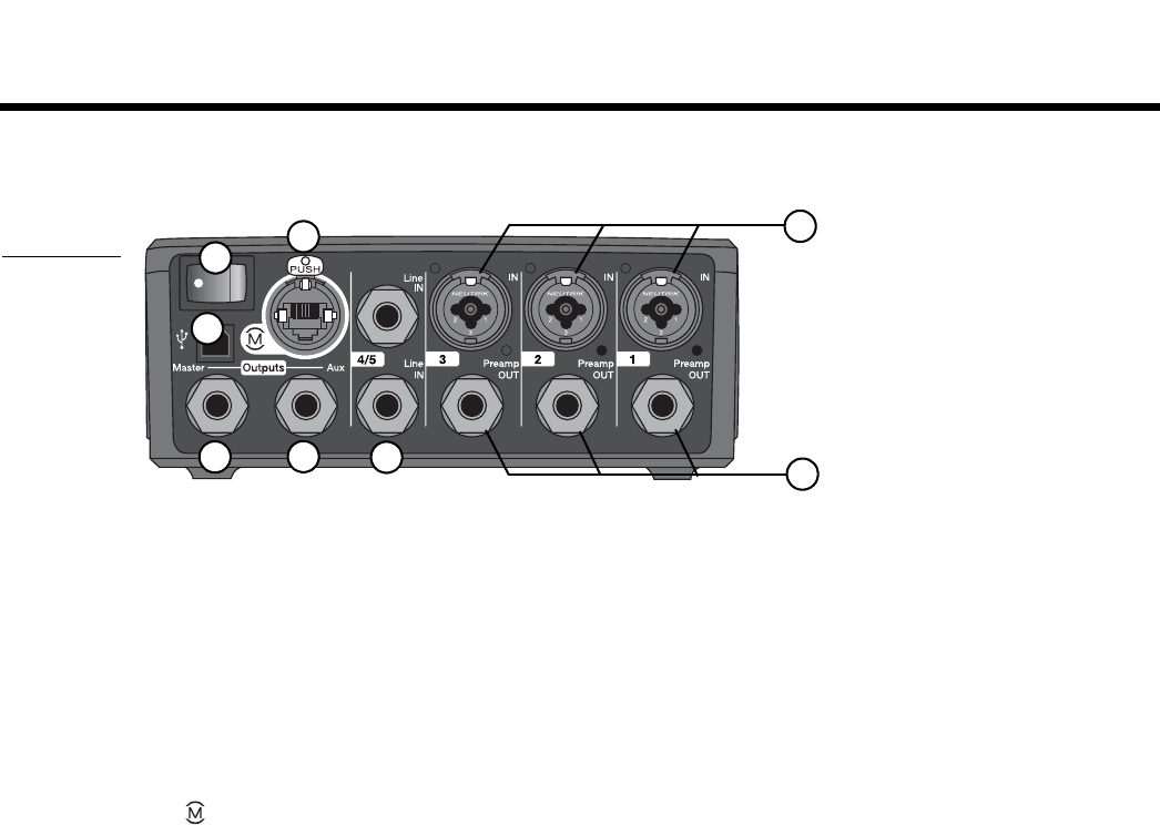
Connection panel
The rear panel provides all input/output connections.
Figure 3
T1 connector
panel
1. IN – Analog input channels 1-3. Accepts XLR balanced cables for microphones, or ¼" TRS balanced or TS
unbalanced cables for high-impedance inputs such as guitars.
2. Preamp OUT – Preamp outputs for channels 1-3. Accepts ¼" TRS balanced or TS unbalanced cables.
3. Line IN – Analog input channels 4/5. Accepts ¼" TRS balanced or TS unbalanced cables for line-level inputs.
Can be used for stereo input signals.
4. Aux Output – User-definable analog output. Can be configured for a pre-fader, post-EQ, and effects, or post-
fader output. Accepts ¼" TRS balanced or TS unbalanced cables.
5. Master Output – User-definable analog output. Can be configured for a pre- or post-Master volume analog
output. Accepts ¼" TRS balanced or TS unbalanced cables.
6. USB port – A USB interface that allows you to connect the T1 to your computer. This feature enables you to
stream audio to/from your computer, update the T1, and back up performance scenes.
7. Power switch – Turns the T1 audio engine on or off.
8. – ToneMatch
TM
port – A digital output used by the L1
TM
model II system. Also delivers power to the T1
audio engine from the L1 model II power stand. Accepts the included ToneMatch
TM
cable.
CAUTION: Although the ToneMatch port accepts a standard RJ-45 connector, DO NOT connect the T1 to a computer
or phone network.
2
3
6
5
7
1
4
8