
Operation Manual


Table Of Contents
- Introduction
- Welcome
- Product overview
- Controls and indicators
- Connection panel
- System Setup
- Unpacking
- Removing/attaching the cover
- Mounting options
- Connecting the T1 to an L1TM model II power stand
- Connecting the T1 to an L1 model I power stand
- Connecting the T1 ToneMatchTM audio engine power supply (optional)
- Connecting the T1 to your computer
- Operating Instructions
- Optimizing input gain and output volume
- Using the Master volume control
- Muting a channel
- Muting channel effects
- Reading the T1 display
- Using the T1 rotary selector
- Editing the sound of a channel
- Selecting a ToneMatch™ preset
- Adjusting zEQ
- Adjusting Para EQ
- Using compressor/gate functions
- Using the KickGate
- Using modulation effects
- Adding delays
- Adding reverb
- Routing input signals to the Aux output
- Using the tuner
- Using global functions
- Selecting a type of reverb
- Using the Prefs utilities
- Loading and saving scenes
- Sharing a scene
- Bose scenes
- Factory Settings
- Singer/Songwriter
- DJ/Playback
- Drums and Bass
- The Works scene
- Factory Settings
- Care & Maintenance
- Cleaning
- Limited Warranty and Registration
- Accessories
- Troubleshooting
- Technical information
9
SYSTEM SETUP
SvenskaItalianoFrançaisEspañolDeutschDanskEnglish Nederlands
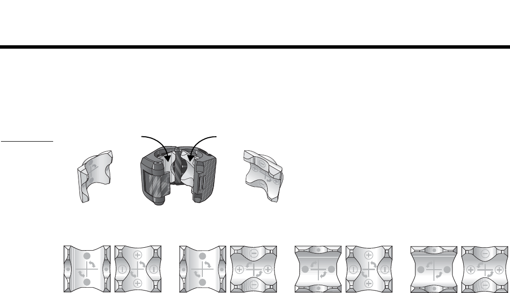
Mounting the T1 on a microphone stand (optional)
The T1 ToneMatch
TM
audio engine microphone stand bracket allows you to mount the T1 on the shaft of most
microphone stands. For installation help, refer to the Quick Setup Guide that came with the bracket.
The bracket uses rotatable inserts which, when properly placed, provide a tight fit on the microphone stand shaft.
Figure 5 shows insert placements for some common shaft diameters. You may need to arrange these inserts differ-
ently for your particular music stand.
Figure 5
Bracket and
insert
placements
Removable insert
A
Removable insert
B
For 22 mm diameter For 20.5 mm diameter For 16 mm diameter For 14.5 mm diameter
AB
AB
AB
AB