
Installation manual


GEM INSTALLATION MANUAL DOCUMENT No. 070906 REV. 1.3
INSIGHT
INSTRUMENT CORP.
10 BOX 122, FORT ERIE, ONTARIO, L2A 5M6
Installing the Exhaust Gas Temperature Probes
The Exhaust Gas Temperature (EGT) probe is designed fit into a hole in each exhaust stack and be secured
with an integral stainless steel clamp.
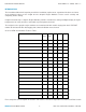
It is important that each probe is mounted a uniform distance from the exhaust stack flange. For normally aspi-
rated engines, a nominal distance of 2 to 3 inches from the flange is recommended.
For turbo-charged engines, a nominal distance of 4 to 5 inches is recommended. See Drawing No. 8254.
If the recommended distance is impractical because of obstructions, slip joints, or bends in the exhaust sys-
tem, position all the probes a uniform distance from the flange as space permits.
It is more important that all probes be positioned at a uniform distance from the flange rather than meeting the
preferred dimension. Probe locations closer to the flange may result in slightly higher (inconsequential)
temperature indications. (Careful matching of probe position will provide best temperature readings.)
If the probe must be positioned in a slip joint the inner tube must have a clearance hole of at least 1/4”
diameter to prevent it from shearing the probe. Be certain to locate all holes to allow straight-in insertion of the
probe without bending or stressing the probe tip.
Before drilling, ensure that nothing interferes with the probe, clamp, clamp screw or wire. Center punch and
pilot drill each hole in the exhaust stack with a No. 28 or 9/64” drill bit. Use caution while drilling perpendicular
to the stack to prevent an elongated hole. NOTE: Tighten the clamp screw with hand-torque nut driver only.
A right angle drill extension may be necessary in some locations. The probe will slip into a carefully drilled hole
and make a tight seal.
Installing the Cylinder Head Temperature Probes
There are three types of Cylinder Head Temperature (CHT) probes:
· Spring Probe (Part Number 2852)
· Spark Plug Gasket Probe (Part Number 2853)
· Adapter Probes (Part Numbers 2855 Bayonet Adapter, and 2856 Threaded Adapter)
The Spring Probe (Part Number 2852) is equivalent to the “old style” Bayonet Probe and screws into threaded
thermo-wells in the cylinder head next to the lower spark plug (on top in some engines).
The Spark Plug Gasket Probe (Part Number 2853) replaces the copper 18 mm diameter spark plug gasket.
The Bayonet Adapter Probe (Part Number 2855) screws directly into the temperature well and replaces the
standard bayonet adapter to allow simultaneous utilization of the factory-installed Bayonet Probe.
The Threaded Adapter Probe (Part Number 2856) is similar to the 2855 except it is threaded on the inside to
allow simultaneous utilization of the factory-installed Threaded CHT Probe.