GEM INSTALLATION MANUAL DOCUMENT No. 070906 REV. 1.4 CHECK WIRING HARNESS BEFORE INSTALLATION Easier/cheaper to check and recheck all harness's and connections than repairing them later! INSTALLATION MANUAL FOR GEM P/N 610C-001 and P/N 1200C-001 Models G1, G2, G3 and G4 DOCUMENT No. 070906 READ THESE INSTRUCTIONS COMPLETELY BEFORE PROCEEDING WITH INSTALLATION Insight Instrument Corporation • Box 122 Fort Erie, ON L2A 5M6 Tel: 905-871-0733 • Fax: 905-871-5460 • Web: www.insightavionics.
GEM INSTALLATION MANUAL DOCUMENT No. 070906 REV. 1.4 If You Read Nothing Else Read This! Follow these recommendations to minimize installation related problems. USE CAUTION when crimping the terminals onto the end of the GEM harness. Test each crimp by tugging on it sharply. It is almost impossible to pull off a properly crimped terminal. KEEP the GEM harness at least 1 inch away from the ignition harness, P-leads, and alternator wiring.
GEM INSTALLATION MANUAL DOCUMENT No. 070906 REV. 1.4 Read This Too! GEM Fuel Totalizer Cautionary Notice Please note that not all GEM models provide fuel data. The Fuel Remaining display on the GEM is very useful but is not without limitations. Understand first that the factory fuel quantity gauges are the only instruments in the panel that physically measure fuel level. They are still the primary indication of fuel level in the airplane.
GEM INSTALLATION MANUAL DOCUMENT No. 070906 REV. 1.4 Table of Contents IF YOU READ NOTHING ELSE READ THIS! ........................................................................... 2 GEM INSTALL LOCATION CAUTIONARY NOTICE .................................................................. 2 GEM FUEL TOTALIZER CAUTIONARY NOTICE ...................................................................... 3 GEM REDLINE CAUTIONARY NOTICE .............................................................................
GEM INSTALLATION MANUAL DOCUMENT No. 070906 REV. 1.4 Table of Contents POWER AND GROUND CONNECTIONS ................................................................................ 16 EGT PROBE WIRING ............................................................................................................... 16 CHT PROBE WIRING ............................................................................................................... 17 ROUTING THE CHT/EGT/TIT WIRING HARNESS .......................
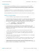
GEM INSTALLATION MANUAL DOCUMENT No. 070906 REV. 1.4 INTRODUCTION This Installation Manual will acquaint you with the installation requirements, operational functions and some of the powerful features of the Insight G-series Graphic Engine Monitors (GEM). Please read it carefully and completely before starting. Insight Instrument Corp.’s Graphic Engine Monitors provides simultaneous analog and digital display of engine temperatures for nearly all makes and models of piston-powered aircraft.
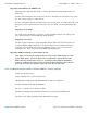
GEM INSTALLATION MANUAL DOCUMENT No. 070906 REV. 1.4 Installation Planning Plan the location of the GEM display such that it is not positioned near any source of high electrical current and is easily visible by the pilot. If the GEM is to be used as a primary engine instrument it is essential to locate it high in the instrument panel and within the pilot's normal instrument scan.
GEM INSTALLATION MANUAL DOCUMENT No. 070906 REV. 1.4 Upgrade Installations GEM upgrade kits are designed to utilize existing Insight Instrument Corp. EGT/CHT/TIT/OAT wiring and probes that are already installed in the aircraft. Prior to ordering an upgrade kit, inspect the aircrafts existing GEM wiring and probes for condition, suitability, and length for use with the new GEM. If an existing harness is not suitable for upgrade use, new replacement harnesses are available from Insight.
GEM INSTALLATION MANUAL DOCUMENT No. 070906 REV. 1.4 Upgrading from GEM 610 or GEMINI 1200 Upgrading from models 610 or 1200 is similar to upgrading from 602 or 603 with a few differences. Previous 610 installations will already have all holes drilled for panel mounting a G1, G2 or G3. G4 models require a 3.125 inch hole. Previous installations of 610 and 1200 models may already have an Insight OAT probe and wiring that can be retained and connected to a G-series GEM. See wiring drawing 610C315.
GEM INSTALLATION MANUAL DOCUMENT No. 070906 REV. 1.4 Unpacking the Graphic Engine Monitor Display ·Carefully inspect the contents of this package for damage. If damage is found, save all packaging so that a claim can be made against the carrier. · Inspect the contents of the shipment to ensure that all component parts and materials have been supplied. · Visually inspect all components for proper identification or damage. ·Immediately report any discrepancies to the Insight Customer Service Department.
GEM INSTALLATION MANUAL DOCUMENT No. 070906 REV. 1.4 If the probe must be positioned in a slip joint the inner tube must have a clearance hole of at least 1/4” diameter to prevent it from shearing the probe. Be certain to locate all holes to allow straight-in insertion of the probe without bending or stressing the probe tip. Before drilling, ensure that nothing interferes with the probe, clamp, clamp screw or wire. Center punch and pilot drill each hole in the exhaust stack with a No.
GEM INSTALLATION MANUAL DOCUMENT No. 070906 REV. 1.4 The Spark Plug Gasket must be removed and replaced by the Gasket Probe. Annealing of the Gasket Probe is not required or recommended, and the Gasket Probe Does Not require replacement when the spark plugs are changed. Alternatively, an Adapter Probe may be used instead of a Gasket Probe. An adapter probe will allow both displays to derive their CHT readings from the same thermo-well.
GEM INSTALLATION MANUAL DOCUMENT No. 070906 REV. 1.4 The Probe Type 2872 Boss fits in a 1/2” inch hole and should be welded by an approved exhaust repair facility. Locate and drill the probe hole as described in Section “INSTALLING THE EXHAUST GAS TEMPERATURE PROBES”, and refer to Drawing No. 8254 for the recommended location. NOTE: If you have questions as to the correct type or location of TIT probes, call Insight Product Support for technical assistance.
GEM INSTALLATION MANUAL DOCUMENT No. 070906 REV. 1.4 may be installed to allow connection of a 7-pin cable to a 6-pin Vibration Sensor, or 7-pin connectors may be removed from service and new 6-pin connectors installed, consult Insight for details. Aircraft with 24 Volt (28 Volt) electrical systems require a 750 Ohm resistor installed in series with the vibration sensors power supply wire. The sensor should be mounted to an engine case bolt on the top of the engine as close to the propeller as practical.
GEM INSTALLATION MANUAL DOCUMENT No. 070906 REV. 1.4 Installing the Fuel Flow Signal Adapter (for Aircraft with an existing Flow Sensor) The GEM is supplementary for fuel flow. Aircraft equipped with existing FF sensors may or may not be compatible with the GEM's Fuel Flow signal inputs. An existing sensor may be part of a primary FF Instrument or it may be supplementary. If the existing FF sensor is primary it should remain in the aircraft to preserve the primary FF instrumentation.
GEM INSTALLATION MANUAL DOCUMENT No. 070906 REV. 1.4 Note: Plan your Installation to include a service loop in the GEM wiring harness to allow for future adjustments. Wires for the supplemental features are supplied pre-terminated at the sensor end, but must be terminated at the instrument end during installation. The D-sub connectors (25 and 37 pin) utilize crimp pins, see the materials section for recommended tooling.
GEM INSTALLATION MANUAL DOCUMENT No. 070906 REV. 1.4 CHT Probe Wiring The CHT temperature probes must be wired with the correct polarity. The CHT probes connect to the harness wires with the black jacket. The probe leads and harness wires are color coded (red and white) to facilitate correct polarity. Each wire is marked with the cylinder number. Slide the wire marker down the wire so it remains with the installation for trouble-shooting. Strip the wires according to Drawing No. 8254.
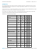
GEM INSTALLATION MANUAL DOCUMENT No. 070906 REV. 1.4 Use the proper tools listed in the Tools and Materials section to crimp and insert the pins into the D-sub connector body. The Feature Table on page six indicates the supplementary features available for each GEM model. The G1 GEM has no P2 connector, all connections are made through P1. The G2, G3, and G4-001 GEM's have a 25-pin D-sub connector, refer to Drawing No. 610C-315 (Pages 1-3).
GEM INSTALLATION MANUAL DOCUMENT No. 070906 REV. 1.4 GEM Configuration Pages G1 GEM's are NOT field-configurable so it is essential to supply all the essential aircraft engine data to Insight at the time of placing the GEM sales order. Failure to provide the correct configuration data will require the G1 GEM to be returned to the factory.
GEM INSTALLATION MANUAL DOCUMENT No. 070906 REV. 1.4 WEIGHT and BALANCE DATA 1 G-series GEM Instrument 0.5 lb 6 Clamp EGT Probes 9 oz. 6 Spring CHT Probes 6 oz. 6 Gasket CHT Probes 4 oz. 1 Adapter CHT Probe 1 oz. 1 TIT Probe 1 oz. 1 Oil Temperature Probe 1 oz. 1 Oil Pressure Sensor 2 oz. 1 Vibration Sensor 1 oz. 1 Fuel Flow Sensor 6 oz. 1 FF Signal Adapter 1 oz. 1 Carburetor Temperature Probe 1 oz. 1 8 ft Wiring Harness 14 oz. 1 24ft Wiring Harness 34 oz.
GEM INSTALLATION MANUAL DOCUMENT No. 070906 REV. 1.4 Symptom: One or more columns will not illuminate. Cause: Check the probe connections, the display will blank columns with poor EGT and CHT connections. Columns 5 and 6 shouldn’t illuminate on a 4 cylinder engine. Check the probe diagnostic page. Symptom: No EGT in one or more columns. Cause: Errors in harness wiring. Visually check probe connections and polarity. Check the probe diagnostic page or measure the resistance of the lead wire manually.
GEM INSTALLATION MANUAL DOCUMENT No. 070906 REV. 1.4 Symptom: Display is affected by radio transmissions. Cause: Proximity of probe and/or display unit to the radio power wiring and away from radios and antenna coax. Check radio rack connector for missing 50 ohm matching device. The 50 ohm matching device is a thick washer-like component part that is installed underneath the connector end cap. The end cap will have to be unsoldered to check for the matching device.
GEM INSTALLATION MANUAL DOCUMENT No. 070906 REV. 1.4 Drawings Drawing No.
GEM INSTALLATION MANUAL INSIGHT INSTRUMENT CORP. DOCUMENT No. 070906 REV. 1.
GEM INSTALLATION MANUAL INSIGHT INSTRUMENT CORP. DOCUMENT No. 070906 REV. 1.
GEM INSTALLATION MANUAL INSIGHT INSTRUMENT CORP. DOCUMENT No. 070906 REV. 1.
GEM INSTALLATION MANUAL INSIGHT INSTRUMENT CORP. DOCUMENT No. 070906 REV. 1.
GEM INSTALLATION MANUAL INSIGHT INSTRUMENT CORP. DOCUMENT No. 070906 REV. 1.
GEM INSTALLATION MANUAL INSIGHT INSTRUMENT CORP. DOCUMENT No. 070906 REV. 1.
GEM INSTALLATION MANUAL INSIGHT INSTRUMENT CORP. DOCUMENT No. 070906 REV. 1.
GEM INSTALLATION MANUAL INSIGHT INSTRUMENT CORP. DOCUMENT No. 070906 REV. 1.
GEM INSTALLATION MANUAL INSIGHT INSTRUMENT CORP. DOCUMENT No. 070906 REV. 1.
GEM INSTALLATION MANUAL INSIGHT INSTRUMENT CORP. DOCUMENT No. 070906 REV. 1.
GEM INSTALLATION MANUAL INSIGHT INSTRUMENT CORP. DOCUMENT No. 070906 REV. 1.
GEM INSTALLATION MANUAL INSIGHT INSTRUMENT CORP. DOCUMENT No. 070906 REV. 1.
GEM INSTALLATION MANUAL INSIGHT INSTRUMENT CORP. DOCUMENT No. 070906 REV. 1.
GEM INSTALLATION MANUAL INSIGHT INSTRUMENT CORP. DOCUMENT No. 070906 REV. 1.
GEM INSTALLATION MANUAL INSIGHT INSTRUMENT CORP. DOCUMENT No. 070906 REV. 1.
GEM INSTALLATION MANUAL INSIGHT INSTRUMENT CORP. DOCUMENT No. 070906 REV. 1.
GEM INSTALLATION MANUAL INSIGHT INSTRUMENT CORP. DOCUMENT No. 070906 REV. 1.
GEM INSTALLATION MANUAL DOCUMENT No. 070906 REV. 1.4 Technical Support If you have difficulty installing or using a G Series system, please read the G series documentation. Every G Series system is shipped with complete instructions for installation and use on a CD. You may also find the same information on our website www.insightavionics.com under Documentation. The answers to many technical questions can be found in these documents.