User’s Manual BV9F 9” FLIP-DOWN WIDESCREEN TFT VIDEO MONITOR WITH BUILT-IN INFRARED AUDIO TRANSMITTER BV9F 9” FLIP-DOWN WIDESCREEN TFT VIDEO MONITOR WITH BUILT-IN INFRARED AUDIO TRANSMITTER 11.2010 BOSS Audio Systems 3451 Lunar Court • Oxnard, CA 93030 www.bossaudio.com tech support: www.bossaudio.com/support 800.999.
SPECIFICATIONS Power Requirements DC 12V Power Consumption 6W Screen Size 9 inch TFT LCD Screen Format 16:9 Wide Resolution Pixel 480xRGBx234 A/V Inputs 2 A/V RCA Inputs Dimensions (L)9.6 (W)9.8 (H)1inch IR Power Requirements DC 12V IR Power Consumption 3W IR Transmitter Frequency A Right 2.8MHz IR Transmitter Frequency B LCD Panel Type Right 3.8MHz Left 3.2MHz Active Matrix TFT Compatible video standard N T S C / PA L a u t o s e l e c t Left 2.
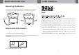
MONITOR OPERATION , USER S MANUAL Releasing the Monitor Push the open button (located on the front edge of the screen housing) a n d l o w e r t h e m o n i t o r t o t h e d e s i r e d a n g l e . Yo u c a n a l s o a d j u s t t h e swivel angle. BV9F PUSH BUTTON How to watch the monitor 1.Connect the monitor to the external devices.
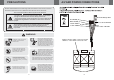
PRECAUTIONS A/V AND POWER CONNECTIONS , Please read and observe all warnings and instructions in this owner s manual and those marked on the unit. Retain this booklet for future reference. There are two kinds of alarm symbols as follows: The lightning flash with arrowhead symbol within an equilateral triangle is intended to alert the user to the, presence of dangerous voltage within the product s enclosure that may be of sufficient magnitude to constitute a risk of electric shock to WARNING people.
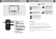
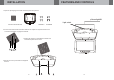
FEATURES AND CONTROLS PRECAUTIONS CAUTION Watching the monitor for an extended period of time with the engine turned off may deplete the vehicle s battery. ............... ............... ............... ............... Power switch ............... Quality installations are best performed by qualified and certifled installers. Menu Remote control This product is designed for operation with a 12 Volt DC, negative ground vehicle. It is not suitable for operation under other conditions or voltages.
INSTALLATION FEATURES AND CONTROLS 1.Open the packaging and check that these parts are present. Dome light/IR Light switch INSTALLATION PLATE UNIT SCREW A SCREW B 2.Connect the external devices RCA cable or AV output as required. Refer to the connection diagram on page 8 for details. ................ ................ ........ ................ 3.Match the position of installation bracket and installation plate with screw A. 4.Secure the unit in place with the supplied screw B.