User manual
Table Of Contents

VETTA Theory of Operation………………Line 6 confidential ……………………………. Page 14 of 18
Z-SELECT status reading (CURRENTLY UNUSED)
The status of the Z_SELECT signal can be read by the microprocessor U27 through the circuit
made of Q6 and Q9 (page 8 of 8 of the Main PCB). The reading is done in two paths.
- First the BDN-DDATA3 line is read while the Option_Sel_3* line is held low. This first
reading brings bit 0 of the Z_Select status.
- The BDN-DDATA3 line is read again while the Option_Sel_3* line is held high. This
second reading brings bit 1 of the Z_Select status.
- The status of the Z_Select is then determined as follows
Bit 0 Bit 1
4 Ohm (+15V)0 1
8 Ohm (open) 1 1
16 Ohm (-15V) 1 0 (used only on VETTA Head)
GUITAR/LINE*_SELECT (USED ONLY WITH OPTION BOARD PRESENT)
This output control line, generated by an I/O pin of DSP #1, controls the analog switch made of
U15 and U22 (page 7 of 8 in Main PCB) and selects which one of the GUITAR or LINE jack
(on the option board) is active. A high level (3.3V) selects the GUITAR jack and a low level
selects the LINE jack. Due to the possible presence of different DC offset level on each input
an audio click could appears on the output when this signal is switched. To avoid this the
following switching sequence is used:
1) Ramp the amplitude of the DSP audio path to 0 over approximately 20ms second
2) Switch the GUITAR/LINE_SELECT Line.
3) Ramp the amplitude of the DSP audio path back to its original level over approximately
20ms second
NOTES:
- On all three VETTA versions the LINE INPUT is available only if a DIG I/O card is installed. Therefore if a
DIG I/O card is not installed the GUITAR / LINE selection page is not available on the menu.
RESET-IO*
This output line, generated by an I/O pin of DSP #1, resets the main ADC, both DACs, the
effect loop CODEC, and the option card (when present). It is pulsed low for a few
microseconds as soon as the firmware starts to run.
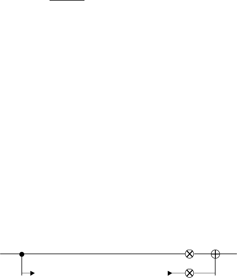
FX_RET_SENSE
This input signal, generated by effect return ¼” jack J10 (page 6 of 8 of the Main PCB), is read
by an I/O pin of the DSP #1. It is high when a jack is plugged in the FX LOOP RETURN jack
and low otherwise. When no jack is sensed on this input (= low), the DSP Direct Level on the
diagram below is set a 1 and the Effect Level at zero.
FX LOOP SEND FX LOOP RETURN
Direct level
Effect level


