
User manual


Table Of Contents
Page 8 of 51 Vetta Head Assembly Instructions Rev D1
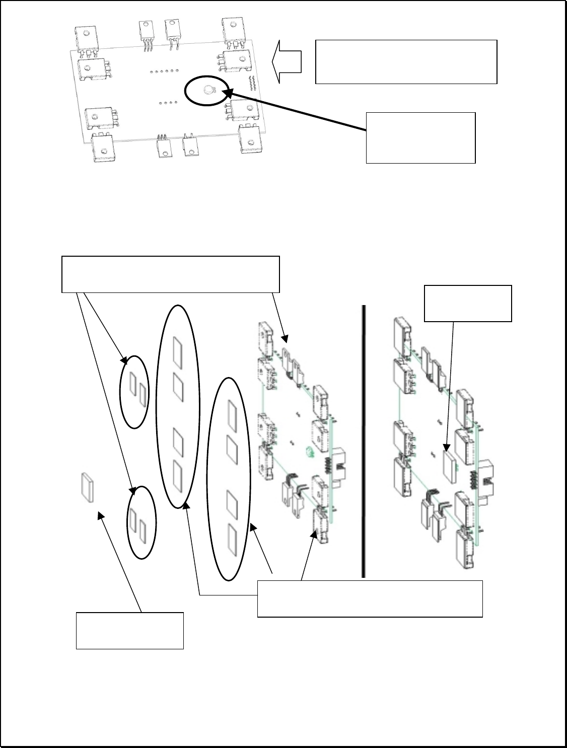
Install thermistor on bottom side of PCB. Solder down with minimum lead length then bend
down toward the center of the PCB (see figure above). Apply the thermal pads flat against the
power components and thermistor as shown in the figure below. Be sure to fully cover the
device with the pads.
T0-247 pads _30-63-4001
- applied to the 8 large power devices
T0-220 pads 30-63-4005
- applied to the 4 small power devices
Gap pad
30-63-5050
Gap pads (
3 per
)
30-63-5050
Orient power components as
shown in figure
Thermistor – note
orientation when
bent down.