
User manual


Table Of Contents
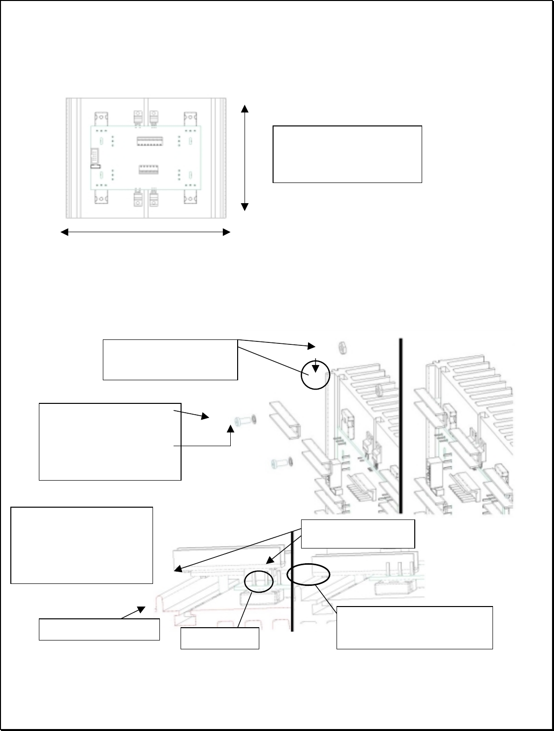
Page 9 of 51 Vetta Head Assembly Instructions Rev D1
c) Attach the Power Amp PCB to the Heat Sink
Remove the adhesive backing from the thermal pads attached to the power devices in the
previous step. Attach the PCB onto the surface of the heat sink centering it vertically and
horizontally as shown below.
d) Secure PCB Assy with the device clamps.
Finish securing the PCB assy to the heat sink using the device clamps. 10 clamps (30-51-0073)
will be used to secure the board. Each clamp is secured using a #8 Socket head cap screw
(“SHCS”) (30-00-0010), lock washer (30-03-0002) and hex nut (30-06-0007). Tighten to a
torque of 10-12 in/lbs.
Center the PCB assy to the
heat sink vertically and
horizontally
Hex nut (30-06-0007)
Slide nut through T-slot
8-32 SHCS, 30-00-0010
Lock washer, 30-03-0002.
Ridges on the underside of
clamp engage the ridge on the
heat sink and slots in the PCB
when the device is correctly
mounted.
Ridges on underside of
clam
p
Ridge on edge of heatsink
Slot in PCB
Note: ridge on clamp butts against
heatsink ridge when correctly
mounted