
User manual


Table Of Contents
Page 10 of 51 Vetta Head Assembly Instructions Rev D1
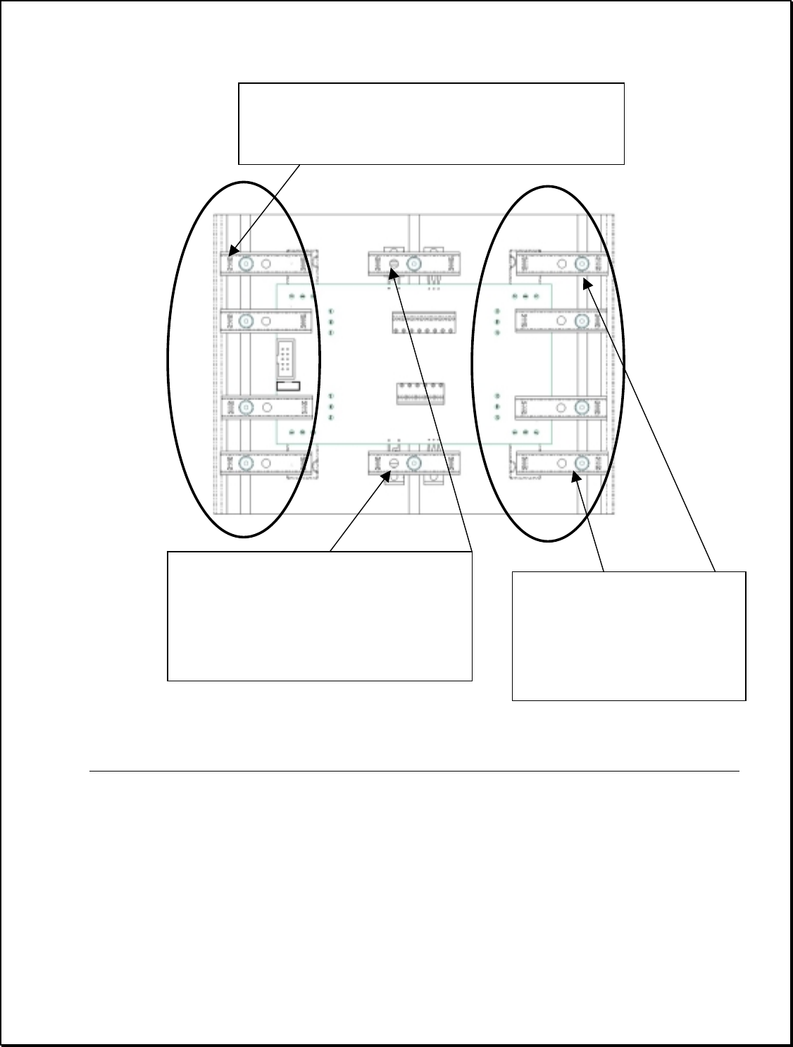
View when fully secured:
To secure each device clamp follow the figure below. Note the 8 edge clamps bolt though the
side hole on the clamp while the 2 central clamps bolt though the central hole in the clamp.
When the device clamps are secured the Power Amp assembly is complete
Remainder of this page intentionally left blank.
NOTE 1
: for these 8 clamps, the SHCS passes
though the edge hole in the device clamp when
securing to the heat sink
NOTE 2
: for these 2 clamps, the SHCS
passes though the center hole in the
clamp.
These also use 2 Washers (# 30-
03-0002) per, otherwise the screw will
bottom out on the heatsink.
NOTE 3:
The corner clamps
on both sides secure only to
the power device and not to
the PCB. Keep the clamps
close to PCB side of the
device.