
User manual


Table Of Contents
Page 12 of 51 Vetta Head Assembly Instructions Rev D1
a) PCB Assembly
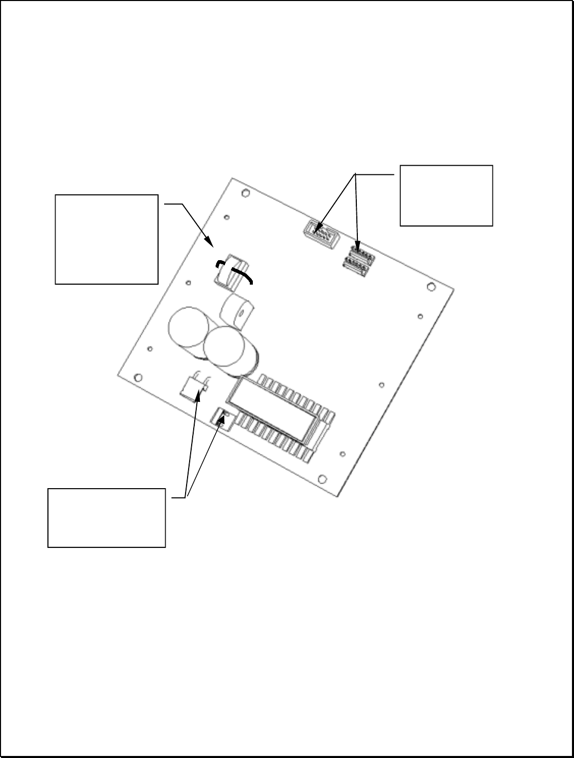
Power Supply Board: (35-00-4000)
a) Check orientation of all headers. All headers must be mounted flush to PCB.
b) Check orientation of all electrolytic capacitors.
c) Check for solder bridges between pins of all through-hole components.
d) Verify that the correct parts were installed for all through-hole transistors.
e) Install D5 & D10 with vertical lead preparation.
The center pin of
these 3 pin headers
Shall be pulled.
Use 20-gauge solid
wire UL Approved
105 rated for
current sense
transformer
Note
orientation of
Headers