
User manual


Table Of Contents
Page 14 of 51 Vetta Head Assembly Instructions Rev D1
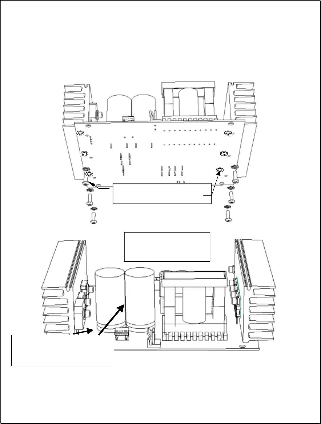
c) Attach Heat Sink / Power Device assembly to PCB
a) Secure Heat Sink assemblies with 6 to 8 in-lbs. of torque then solder the device leads.
b) Apply RTV to large Capacitors (Dow or GE NovaSil or Novagard.) as shown below & in initial assembly
breakdown dwg.
(6) #4-40 SHCS (6) P/N 30-00-0440,
(6) # 4 Split washer (6) 30-03-0400
Apply a 1 inch long Silicone
Bead where the two Capacitors
meet (this side and opposite side)
And at the base.
APPLY RTV SILICON, TO THE
SIDES & BASE OF THE
LARGE CAPS.