
User manual


Table Of Contents
Page 20 of 51 Vetta Head Assembly Instructions Rev D1
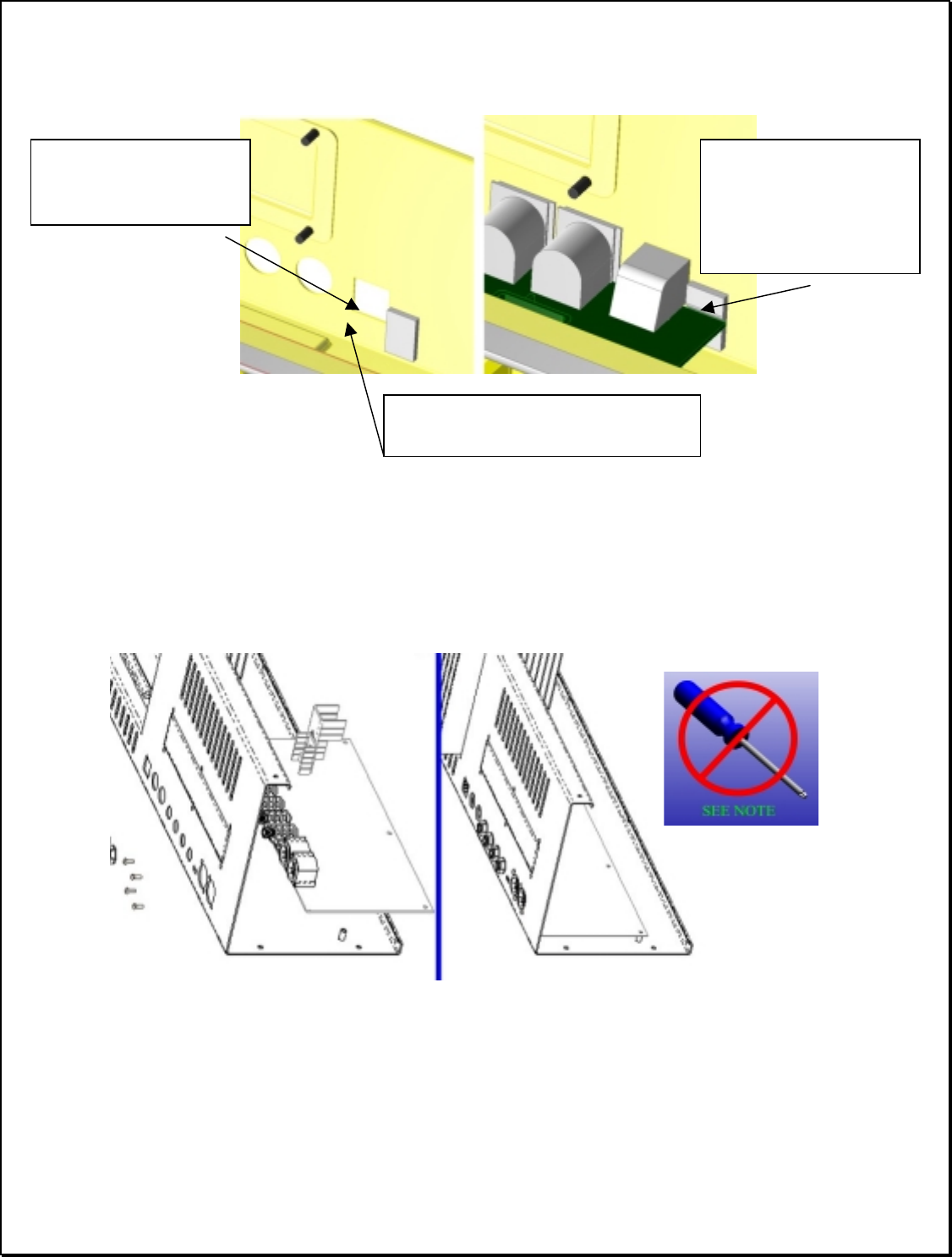
d) Attach Foam Block to the chassis and the Main Board PCB
Cut foam block (#30-75-0010) into 1/3 of length. Attach the block to the indicated position
adjacent to the RJ45 jack opening (just below the expansion slot cover).
The MAIN PCB goes in next. Place the PCB on the PEMs in the chassis and slide the jacks
through the appropriate cutouts as shown.
WHEN CORRECTLY INSTALLED THE JACK
FACES SHOULD PASS THEOUGH THE THOUGH HOLES. ENSURE THE RJ45
PROJECTS THOUGH ITS RESPECTIVE OPENING.
Begin by placing and partially tightening the (3) #6-32 x .375 lg. pan head Phillips screw w/
captive star lock washers (30-00-0607) that attach through the PCB. Tighten these screws only
partially. The back-panel screws MUST be tightened before locking these screws down.
Note: In spite of the warning, a screwdriver may be used to help insert the screws and partially
tighten them, but they must not be fully tightened until after the back panel screws are placed
and tightened. The “No Screwdrivers” graphic is simply to highlight this. The reasons for this
are detailed in the note at the end of this section.
Position so foam block
lies about 1/16 from
hole opening
Position foam about 3/8 in below
this edge
When Main PCB is
installed (next step),
ensure the board
engages foam similar
to this view