
User manual


Table Of Contents
Page 21 of 51 Vetta Head Assembly Instructions Rev D1
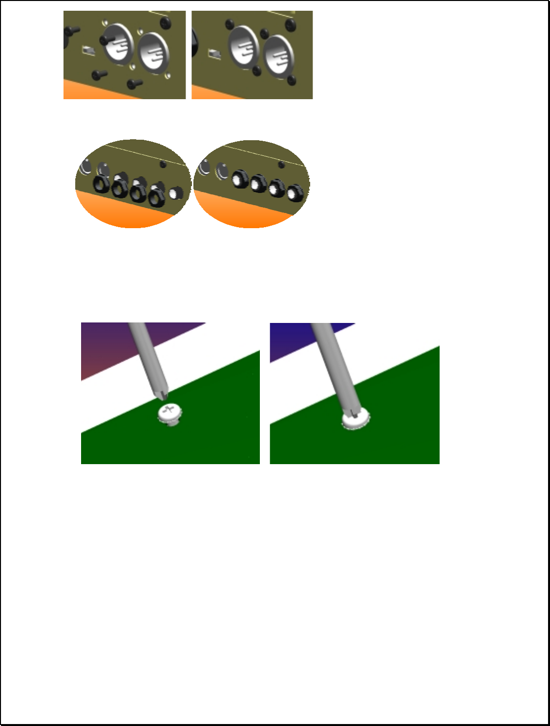
The PCB Screws must now be tightened the rest of the way. They should be tightened to a
torque of 6 in-lbs.
Note: These screws must be left loose until this step for 3 main reasons: (1) It is the easiest
way to get all of the screws to line up. (2) It will help prevent cracking in the solder joints
on the jacks and (3) it will ensure grounding points will make electrical contact with the
chassis.
FYI: If the PCB screws are tightened prior to inserting and tightening the back panel
screws, the fixed board may not align properly, creating high shear stress on the jack pins.
Conversely, if the PCB screws have not been placed and finger tightened to rough locate
the board prior to the back panel screws, there is a possibility of misalignment with the
PEMS. Forcing this misalignment back into alignment while the back panel screws are
tight will have the same effect of heightening shear stress on the jack pins and may crack
the solder joints.
(4) #4 tapping screws (30-
00-4250) hold the XLR
jacks to the back panel.
Flush the jacks with the
back panel, insert the
screws, and tighten to 4
in-lbs.
(4) Plastic jack nuts
should be placed next.
Flush the jacks with the
b
ack panel, insert the nuts,
and tighten to 4-5 in-lbs.