
User manual


Table Of Contents
Page 23 of 51 Vetta Head Assembly Instructions Rev D1
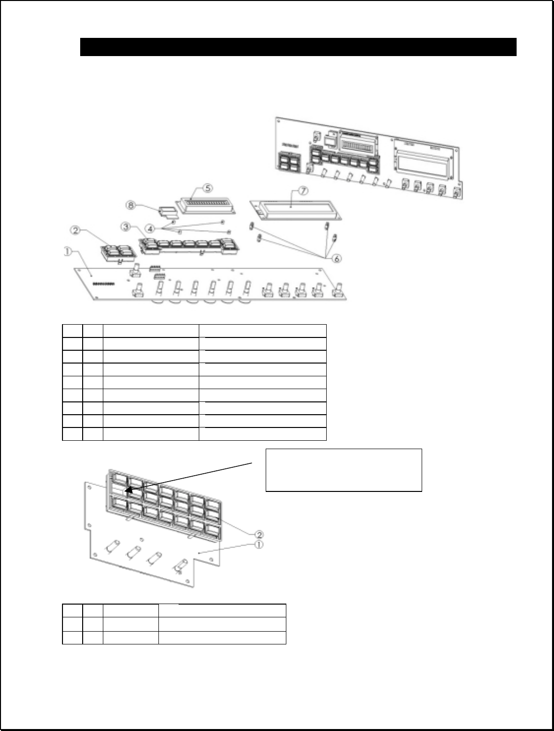
The User Interface (UI) PCBs
Before the user interface PCBs can be attached to the chassis cover, it is first necessary to
assemble the button arrays and LCDs.
ITEM QTY LINE6 PART NO DESCRIPTION
1 1 50-00-0106 PCB ASSY, USER INTERFACE, LEFT
2 1 50-00-0006 ASSEMBLY, AMP SELECT
3 1 50-00-0038 ASSEMBLY, CHANNEL SELECT
4 4 30-12-0001 RICHCO P/N DLCBST-3-01
5 1 50-00-0114 PCB ASSY, DISPLAY, 192 x 48
6 4 30-12-0002 RICHCO P/N LMSP-3-01
7 1 50-00-0115 PCB ASSY, DISPLAY, 1 X 16
8 1 N/A (BREAK AWAY, 50-00-0107) PCB ASSY, LED
ITEM QTY LINE6 PART NO DESCRIPTION
1 1 50-00-0107 PCB ASSY, INTERFACE, USER
RIGHT
2 1 50-00-0031 ASSY, FINAL, EDIT SEL
The UI Right PCB.
Refer to this graphic
throughout the following
section for aid in locating
the parts discussed.
The UI Left PCB
Note empty hole orientation
when mounted on board