
User manual


Table Of Contents
Page 24 of 51 Vetta Head Assembly Instructions Rev D1
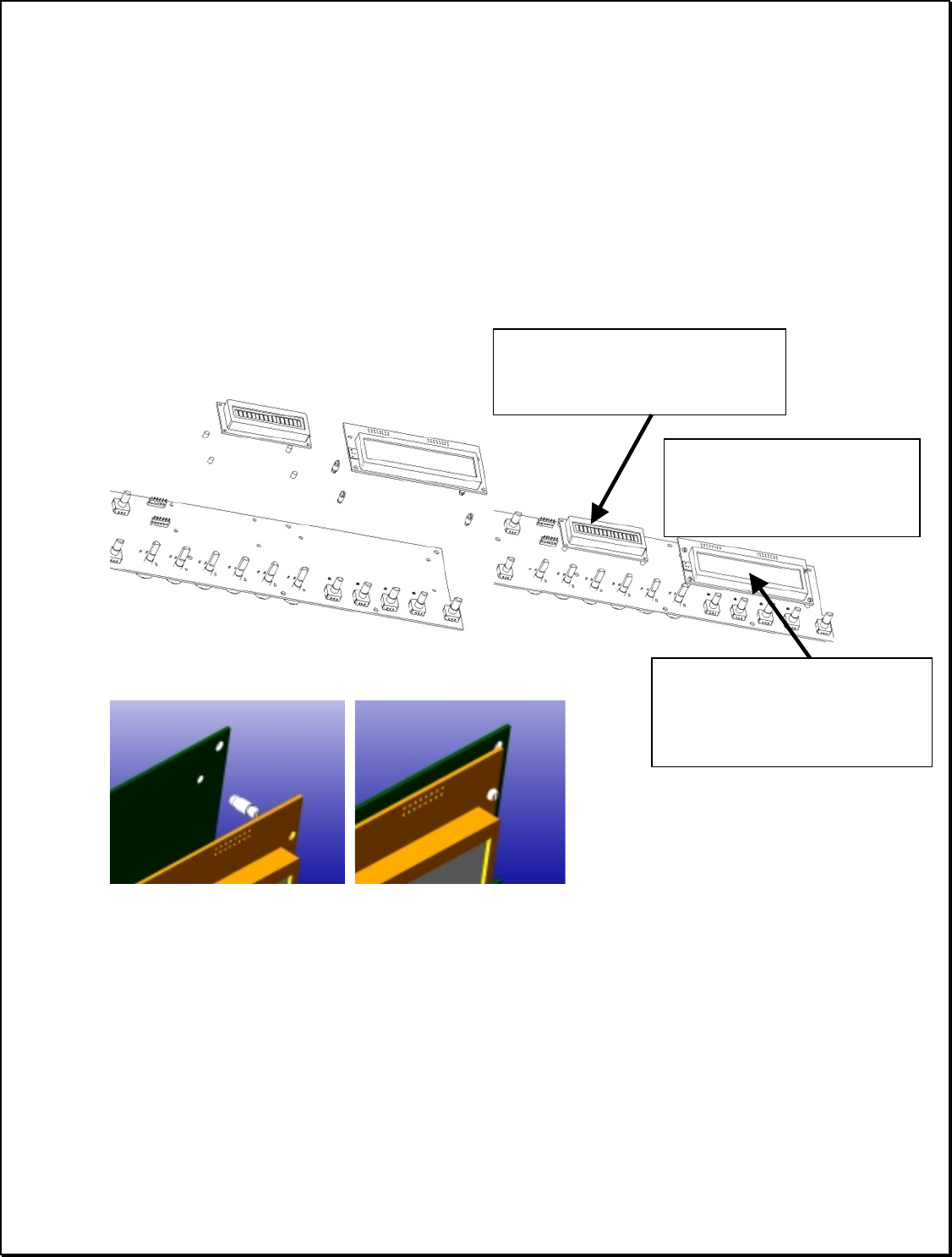
a) Place Standoffs and Displays
The LCDs (50-00-0114) & (50-00-0115) must be attached to the left (larger) PCB. Both
displays are attached with snap-in plastic standoffs. Place the standoffs through the predrilled
holes in the UI board PCB until their locking fingers are fully engaged. After placing four
standoffs for each display, snap the respective display into place on the standoffs.
BOTH
DISPLAY PCB ASSEMBLIES CONTAIN LEADS THAT WILL PASS THROUGH
HOLES AND INTO HEADERS ON THE UNDERSIDE OF THE UI – PCB. ENSURE
THAT THESE LEADS PASS SMOOTHLY THOUGH THE DRILL HOLES
WITHOUT BENDING
. Note foam strip placement , under the small LCD. When snapped in
place, do not solder.
Remove the led PCB assy assembly from the UI board – right (50-00-0107). This is soldered
onto the UI board – left (50-00-0106) at position H2. The LED PCB assembly is mounted onto
the plastic standoff already mounted onto the UI-left (see figure below).
Orient the assembly
according to the figure
. When fully positioned on the standoffs
the face of the led should be at the same level and parallel with the LCD assemblies. Solder
when mounted.
Large LCD assy –
- Standoffs: 30-12-0002
- PCB holes M1,
M2,M3,M4
Small LCD assy –
- standoffs: 30-12-0001
- PCB holes M5,M6,M7,M8
ENSURE ALL LEADS
PASS INTO UI
CONNECTORS WITHOUT
BENDING!!