
User manual


Table Of Contents
Page 25 of 51 Vetta Head Assembly Instructions Rev D1
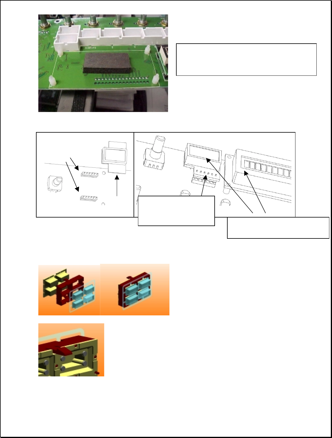
b) Pre-assemble Button Assemblies
The button assemblies must be partially pre-assembled. Each button assembly consists of a
rubber keypad, a plastic isolation frame, and an array of keycaps affixed to a Mylar retainer.
Note: The (3) button assemblies are all assembled in a similar fashion.
The boxed pullout graphic at the left shows the
backside of the button pad assembly. The holes
in the rubber pad mate with the indicator pegs in
the plastic. The Mylar keycap assembly just rests
in place at this stage. The front panel of the
respective model will later retain it.
UI-PCB headers
LED assy
(note orientation)
Solder LED PCB only when these
surfaces are parallel and equal height
Trim leads and cover with
tape specified in the PCB
assy instructions
Small Display Module.
Add 1 Foam piece (approx 1”) #30-75-0010,
Under small Display module #50-00-0115.