
User manual


Table Of Contents
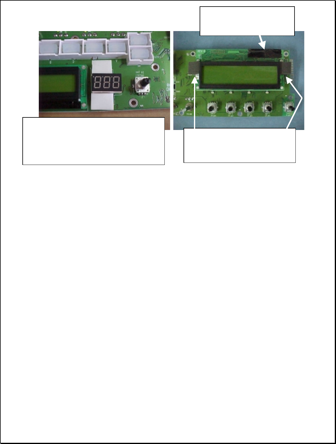
Page 27 of 51 Vetta Head Assembly Instructions Rev D1
d) Inspect the UI PCBs
The UI PCBs should now be completed sub-assemblies. Check to make sure that:
1. All button assemblies are securely snapped in place and depress reliably. Ensure that
Rubber keypads sit naturally under the button frames and are not twisted or deformed
2. All soldered components are securely fixed to the PCB and are mechanically
functional.
• Visually inspect pots and encoders to see that parts are perpendicular to the board
surface. If the stem of a component is skewed, correct the problem immediately.
• Make sure all pots have nuts
•
Make sure 3 out of the 4 pots in the right UI board are center click.
• Lightly pull on the stems of all potentiometers and encoders to ensure that the
component is properly fixed and that the part is not defective (i.e. the stem does not
detach from the component). If a component fails this test, DO NOT attempt to fix
the broken component. Discard and replace the component immediately.
• Spin the stem of each component to verify smooth consistent feel and function.
• Mark the PCBA with the appropriate Assembly Rev letter.
When inspection process is complete, set the front panel PCB sub-assembly aside.
Add 2 White Foam (#30-15-0044) squares
Over Pins of LED display. 2 Strips of
Polyester tape (#30-65-0002), can be added
on top of the foam, or prior to foam
application.
Replace Large display Module.
Add 2 Rubber Pads (#30-75-0010)
As shown.
Polyester Tape (#30-65-0002)
strips should cover these exposed
pins.