
Service manual


MEX-XB100BT
49
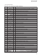
• IC Pin Function Description
MAIN BOARD IC503 R7S7200032CFP (SYSTEM CONTROLLER)
Pin No. Pin Name I/O Description
1 NC - Not used
2 AMP_ATT O Amplifi er muting on/off control signal output to the power amplifi er “H”: muting on
3 AMPSTB O Standby signal output to the power amplifi er “L”: standby
4 SERVO_ON O Power on/off control signal output to the servo section “H”: power on
5 SP_CLK O Serial data transfer clock signal output to the audio DSP
6 SP_DATA I Serial data input from the audio DSP
7 Vcc - Power supply terminal (+1.18V) (for internal)
8 DEC_XMUTE O Muting on/off control signal output to the audio DSP “L”: muting on
9 Vss - Ground terminal
10 CD_ZDET I Zero data detection signal input from the audio DSP
11 PVcc - Power supply terminal (+3.3V) (for I/O)
12 BSIF_GATE O Gate signal output to the audio DSP
13 DEC_INT I Interrupt signal input from the audio DSP
14 DSP_RST O Reset signal output to the audio DSP “L”: reset
15 DSP_SSTBY O Standby signal output to the audio DSP “L”: standby
16 BSIF_ST_REQ I Request signal input from the audio DSP
17 CD_BUSCLK O Serial data transfer clock signal output to the audio DSP
18 Vss - Ground terminal
19 CD_XCCE O Chip enable signal output to the audio DSP
20 CD_SDO O Serial data output to the audio DSP
21 Vcc - Power supply terminal (+1.18V) (for internal)
22 CD_SDI I Serial data input from the audio DSP
23 Vss - Ground terminal
24 BSIF_BCK O Bit clock signal output to the audio DSP
25 PVcc - Power supply terminal (+3.3V) (for I/O)
26 BSIF_LR O L/R sampling clock signal output to the audio DSP
27 BSIF_DO O Audio data output to the audio DSP
28 BEEP O Beep sound drive signal output to the power amplifi er
29 DEC_BCK_IN I Bit clock signal input from the audio DSP
30 DEC_LRCK_IN I L/R sampling clock signal input from the audio DSP
31 Vss - Ground terminal
32 DEC_SDOUT_F O Audio data output to the audio DSP
33 DEC_SDIN_CH0 I Audio data input from the audio DSP
34 Vcc - Power supply terminal (+1.18V) (for internal)
35 LCD_CLK O Serial data transfer clock signal output to the front panel block
36 Vss - Ground terminal
37 NC - Not used
38 LCD_CE O Chip enable signal output to the front panel block
39 PVcc - Power supply terminal (+3.3V) (for I/O)
40 LCD_DO O Serial data output to the front panel block
41 MEC_EJECT O Loading motor drive signal (eject direction) output terminal “H”: motor on
42 SYNC_OUT O Frequency control signal output to the regulator and DC/DC converter
43 DEBUG_TX O Transmit data output terminal for the debug Not used
44 LRCK_INT I L/R sampling clock signal input from the pin 26 (BSIF_LR)
45 ACC_IN I Accessory power detection signal input terminal “L”: accessory power on
46 Vss - Ground terminal
47 DRV_ON O Driver control signal output to the CD mechanism deck block
48 XM_TX O Serial data output to the SIRIUSXM in connector (US and Canadian models only)
49 KEY_ACK1 I Key acknowledge signal (wake up signal) input from the front panel block
50 PVcc - Power supply terminal (+3.3V) (for I/O)
51 MEC_INSW I Disc insert detection switch input terminal
52 BT_CLK I Serial data transfer clock signal input from the BT module
53 BT_SYNC I Sync signal input from the BT module
54 BT_DOUT O Audio data output to the BT module
55 BT_DIN I Audio data input from the BT module
56 BU_IN I Back-up power detection signal input terminal “L” is input at low voltage