ORDER NO.MD0510385C3 DVD Home Theater Sound System SA-HT885WGC SA-HT885WGS Colour (S).......................Silver Type Specifications Type of Emissions: lGeneral Power Source: AC 110/127/220-230/240V, 50/60Hz Power consumption: 25 W Dimensions (W×H×D): 430×60×348.3 mm Mass: 2.7 kg lGeneral (For digital transmitter and receiver) Power Source: AC 110-127/220-240V, 50/60 Hz Power consumption: Digital transmitter 0.3 W Digital receiver 36 W Dimensions (W×H×D): Digital transmitter 97×47.5×8.
SA-HT885WGC / SA-HT885WGS lSurround: PMPO: 60 W/ Channel (6Ω) Comforming to SD VIDEO specifications (ASF standard)/ MPEG4 (Simple Profile) video system/G.726 audio system. 1000 W (12) lFM tuner section Frequency Range: lMaximum number of recognizable audio, picture and video contents and groups: 87.5-108.0MHz (50kHz in step) Sensitivity: 2.5µV (IHF) S/N 26dB 2.2µV Antenna Terminal: 75Ω (non balance) 4000 audio, picture and video contents and 400 groups lExif Ver 2.
SA-HT885WGC / SA-HT885WGS 1. Specifications are subject to change without notice. Mass and dimensions are approximate. 2. Total harmonic distortion is measured by the digital spectrum analyzer. Solder: This model uses lead free solder (PbF). CONTENTS Page 1 Use of Active Subwoofer Page 5 12 Disassembly and Main Component Replacement Procedure 5 1.1. Checking Player when Active Subwoofer is not used 2 Safety Precautions 2.1. GENERAL GUIDELINES 22 6 12.1. Disassembly Procedure 22 6 12.2.
SA-HT885WGC / SA-HT885WGS 14 Optical Pick-up Self-Diagnosis and Replacement Procedure 35 18 Abbreviations 45 19 Voltage Chart 47 14.1. Optical Pickup Breakdown Diagnosis 35 19.1. DVD Module P.C.B. 47 14.2. Service Mode Table 1 36 19.2. Main P.C.B. 48 14.3. DVD Self Diagnostic Function-Error Code 36 19.3. FL P.C.B. & MIC P.C.B & Tray Loading P.C.B. 49 14.4. Service mode table 2 38 20 Wave Form Chart 50 14.5. Sales demonstration lock function 40 21 Schematic Diagram Notes 51 14.6.
SA-HT885WGC / SA-HT885WGS 1 Use of Active Subwoofer 1.1. Checking Player when Active Subwoofer is not used 1. This unit uses the active subwoofer to supply the power of the component, and the active subwoofer should be connected to the component to check operational conditions of the component. 2. If the active subwoofer is not available due to repair of the unit, use the following equipment.
SA-HT885WGC / SA-HT885WGS 2 Safety Precautions 2.1. GENERAL GUIDELINES 1. When servicing, observe the original lead dress. If a short circuit is found, replace all parts which have been overheated or damaged by the short circuit. 2. After servicing, see to it that all the protective devices such as insulation barriers, insulation papers shields are properly installed. 3. After servicing, carry out the following leakage current checks to prevent the customer from being exposed to shock hazards. 2.1.1.
SA-HT885WGC / SA-HT885WGS Caution Be sure no power is applied to the chassis or circuit, and observe all other safety precautions. 8. Minimize bodily motions when handling unpackaged replacement ES devices. (Otherwise harmless motion such as the brushing together of your clothes fabric or the lifting of your foot from a carpeted floor can generate static electricity (ESD) sufficient to damage an ES device).
SA-HT885WGC / SA-HT885WGS 6 Precaution of Laser Diode CAUTION : This product utilizers a class 1 laser. Invisible laser radiation is emitted from the optical pick up lens. When the unit is turned on: Wavelength : 658nm/780nm Maximum output radiation power from pick up : 100µW/VDE Laser radiation from pick up unit is safety level, but be sure the followings: 1. Do not disassemble the optical pick up unit, since radiation from exposed laser diode is dangerous. 2.
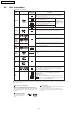
SA-HT885WGC / SA-HT885WGS 8 General Description 8.1. Operating instructions /AV SYSTEM AV SYSTEM TV TV/AV AUX TV/AV AUX 1 2 3 4 5 6 7 8 VCR TUNER/BAND, DVD/CD TUNER/BAND DVD/CD CH CH CH NUMBERED BUTTONS CANCEL 9 VOLUME -/-- 0 CANCEL VOLUME S 10 SLOW/SEARCH SKIP (STOP) TOP MENU MENU DIRECT NAVIGATOR PLAY LIST TOP MENU (SLOW/SEARCH) (PLAY) (SKIP) (PAUSE) MENU ENTER ENTER FUNCTIONS/ TV VOL FUNCTIONS RETURN TV VOL TV VOL SUBWOOFER SUPER SRND C.FOCUS LEVEL H.
SA-HT885WGC / SA-HT885WGS 8.2. Disc information Discs that can be played Disc Logo Indication in these operating instructions RAM Recorded with devices using Version 1.1 of the Video Recording Format (a unified video recording standard), such as DVD video recorders, DVD video cameras, personal computers, etc. JPEG Recorded with Panasonic SD multi cameras or DVD video recorders using the DCF (Design rule for Camera File system) Standard Version 1.0.
SA-HT885WGC / SA-HT885WGS 11
SA-HT885WGC / SA-HT885WGS 8.3. Using of Receiver Unit (SH-FX50) · This model can be equipped with the digital transmitter and receiver to enjoy surround sound wirelessly.. 8.3.1.
SA-HT885WGC / SA-HT885WGS 8.3.2. 8.4. 8.4.1. Tips of using digital transmitter About HighMAT What’s HighMAT? Consumers worldwide are using PCs to create their own collections of music, photos and even video by burning them onto CDs. But how these collections can be experienced across different devices can be confusing to navigate, time consuming to access for a DVD player, and be incomplete in terms of music information available to the customer.
SA-HT885WGC / SA-HT885WGS 8.4.2. Why take advantage of HighMAT? A Problem Defined:Today, when consumers create their own digital audio, video or photo collections on CD-R or other physical formats, there are numerous, inconsistent ways that devices read the data.
SA-HT885WGC / SA-HT885WGS 8.4.3. Benefits of HighMAT? Conventional HighMAT Even though DVD player is CD-R/RW compatible, the inconsistent ways HighMAT compatible products play content back with consistent that various DVD players can read the music or photos files often leads interface. This includes products which are JPEG compatible products to a confusing and inconsistant playback experince. without HighMAT support.
SA-HT885WGC / SA-HT885WGS HighMAT is now available for CD Burning and in Leading DVD Players HighMAT is a new technology that is now available in leading software and consumer electronic devices to dramatically improve the digital media experience when you create homemade CDs HighMAT delivers a simple, standardized way for PC software and consumer electronics devices to talk to each other and work better together.
SA-HT885WGC / SA-HT885WGS When you create your homemade CDs with software that supports HighMAT CD burning, and then play them back on a DVD player that supports HighMAT, you get better, easier navigation. You get folders you can access with a single click of your DVD player´s remote control. You can view important information about your music like full song names, artist titles, album names and genre. And you can get faster startup on your home entertainment device.
SA-HT885WGC / SA-HT885WGS 9 Accessories Remote control AC cord AM loop antenna AC cord (For GS area) FM indoor antenna System cable Video Cable Speaker label Speaker cable 18
SA-HT885WGC / SA-HT885WGS 10 Caution for AC Cord 19
SA-HT885WGC / SA-HT885WGS 11 Handling Precautions for Optical Pickup Unit The laser diode in the optical pickup unit may break down due to static electricity of clothes or human body. Special care must be taken avoid to electrostatic breakdown when servicing and handling the laser diode. 11.1. Cautions to Be Taken in Handling the Optical Pickup Unit The laser diode in the optical pickup unit may be damaged due to electrostatic discharge generating from clothes or human body.
SA-HT885WGC / SA-HT885WGS 11.3.2. Human body grounding 1. Use the anti-static wrist strap to discharge the static electricity form your body.
SA-HT885WGC / SA-HT885WGS 12 Disassembly and Main Component Replacement Procedure “ATTENTION SERVICER” Some chassis components may have sharp edges. Be careful when disassembling and servicing. 1. This section describes procedures for checking the operation of the major printed circuit boards and replacing the main components. 2. For assembly after operation checks or replacement, reverse the respective procedures. Special reassembly procedures are described only when required. 3.
SA-HT885WGC / SA-HT885WGS 12.2. Main Components and P.C.B. Locations.
SA-HT885WGC / SA-HT885WGS 12.3. Disassembling the Top Cabinet Step 1 Unscrew the screw. Step 2 Lift up and remove the top cabinet. 12.4. Disassembling the Lid assembly (When taking out disc manually) · Follow the (Step 1) - (Step 2) of Item 12.3. Step 1 Separates the gear for drawing out tray from the mechanism unit. It inserts a screw driver in the gear. (The gear jig) Step 2 Insert the gear jig into the tray open/ close hole. Step 3 Turn the gear jig counterclockwise to open the tray.
SA-HT885WGC / SA-HT885WGS 12.5. Disassembling the Front Panel · Follow the (Step 1) - (Step 2) of Item 12.3. · Follow the (Step 1) - (Step 3) of Item 12.4. Step 1 Remove the lid assembly from the tray section. Step 2 Detach FFC cables at connectors. (CN2008, CN2009) Step 2 Unscrew the screws. Step 3 Remove the front angle. Step 4 Unscrew the screws. Step 3 Release the tabs. 12.7. Disassembling the DVD mechanism Unit · Follow the (Step 1) - (Step 2) of Item 12.3.
SA-HT885WGC / SA-HT885WGS 12.9. Disassembling the Rear panel · Follow the (Step 1) - (Step 2) of Item 12.3. Step 1 Unscrew the screws. Step 2 Release the tabs. 12.8. Disassembling the DVD Module P.C.B. 12.10. Disassembling Main P.C.B. · Follow the (Step 1) - (Step 2) of Item 12.3. · Follow the (Step 1) - (Step 2) of Item 12.3. · Follow the (Step 1) - (Step 3) of Item 12.4. · Follow the (Step 1) - (Step 3) of Item 12.4. · Follow the (Step 1) - (Step 4) of Item 12.5.
SA-HT885WGC / SA-HT885WGS 12.11. Service Position 12.11.1. Servicing position of the DVD Module P.C.B. · Follow the (Step 1) - (Step 2) of Item 12.3. · Follow the (Step 1) - (Step 3) of Item 12.4. · Follow the (Step 1) - (Step 4) of Item 12.5. · Follow the (Step 1) - (Step 4) of Item 12.7. · Follow the (Step 1) of Item 12.8. · Follow the (Step 1) - (Step 2) of Item 12.9. Step 1 Connect FFC cable at connector. (CN2008, CN2009) Step 2 Turn Mechanism unit to vertically position. 12.11.2.
SA-HT885WGC / SA-HT885WGS 13 Assembling and disassembling the DVD mechanism Unit 13.2. Traverse Unit 1. Slide the lever (A) in the arrow direction (to the opposite side) till it stops. 2. Slide the lever (A) further by bending the tab at the right side of the lever A in the right direction. (The right groove opens and the boss becomes seen.) 13.1. Disassembly Procedure 3. Open the lever (B) to left. (The 2 grooves at the left side open.) 4.
SA-HT885WGC / SA-HT885WGS 13.3. Tray Unit 1. Slide the guide tray unit while pressing the stopper in the arrow direction, and remove the guide tray unit. 5. Remove the drive arm concave phase from the tray slider and tray. (Assembling the tray unit) 2. Raise the loading unit. 1. Insert a part of the tray into the unit sliding over the groove on the mechanical chassis unit. 3. Slide the lever in the arrow direction till it stops and pull the tray out. 2.
SA-HT885WGC / SA-HT885WGS 4. Remove the belt. 13.4. Loading section 5. Unlock the tab and remove the pulley. 6. Remove the relay gear. 1. Spread the tabs at the both sides and push out the drive arm shaft. 7. Turn the change lever in the arrow direction till it stops. 8. Hook the change lever spring on the change lever project part temporarily. 2. Hook the lock lever spring on the lock lever projection part temporarily. 3. Unlock the tab and remove the lock lever.
SA-HT885WGC / SA-HT885WGS 9. Pull the lever (B) in the bottom side to your side and remove the change lever. 13.6. Optical Pickup Unit 13.6.1. Procedure for Disassembling the Optical Pickup Unit 1. Spread the tabs to push in the pin. 10. Remove the drive rack, the sub rack and the drive gear. 2. Remove the pins. 13.5. Tray Loading P.C.B. 1. Unscrew the screws 3. Remove the traverse deck.
SA-HT885WGC / SA-HT885WGS 7. Unscrew the screw 8. Slide the shaft in the arrow direction. 4. Move the optical pickup unit in the arrow direction till it stops. 9. Lift the optical pickup unit with the shaft. 5. Unscrew the screws. 10. Remove the optical pickup unit. 6. Remove the drive rack.
SA-HT885WGC / SA-HT885WGS (Assembling the optical pickup unit) 1. Pass the intermediate FPC through the frame hole. 2. Align the guide section of the optical pickup unit with the rail. 3. Install the shaft top to the holder. 11. Pull the shaft and the rubber out. 13.7. Traverse Motor and Spindle Motor 1. Unscrew the screws. 2. Remove the cover while lifting the inner gear.
SA-HT885WGC / SA-HT885WGS 7. Unscrew the screws with torx screw driver (T6). 8. Remove the spindle motor. 3. Remove the solders. 4. Remove the traverse motor. 5. Remove the solders. 6. Remove the screw lock as carefully as you can.
SA-HT885WGC / SA-HT885WGS 14 Optical Pick-up Self-Diagnosis and Replacement Procedure 14.1. Optical Pickup Breakdown Diagnosis The optical pickup self-diagnosis function and tilt adjustment check function have been included in this unit. When repairing, use the following procedure for effective Self-diagnosis and tilt adjustment. Be sure to use the self-diagnosis function before replacing the optical pickup when "NO DISC" is displayed.
SA-HT885WGC / SA-HT885WGS 14.2. Service Mode Table 1 The service modes can be activated by pressing various button combination on the player and remote control unit. Player buttons STOP Remote control unit buttons 0 5 6 7 DISPLAY 3 PAUSE Application Error code display Tilt adjustment Note (Refer to the item, “14.3. DVD Self Diagnostic Function-Error Code”). Refer to the item “17.4. Optical adjustment”).
SA-HT885WGC / SA-HT885WGS Error Code F890 F891 F893 F894 F895 F896 F897 F898 F8A0 Error Content Sending message when message is being sent to AV task Message couldn’t be sent to AV task FROM falsification EEPROM abnormality Language area abnormality No existence model Initialize is not completed Disagreement of hardware and software Message command is not appropriate Additional error explanation Sending message to AV task Begin sending message to AV task Firm version agreement check for factory preset s
SA-HT885WGC / SA-HT885WGS 14.4. Service mode table 2 Pressing various button combinations on the player and remote control unit can activate the service modes.
SA-HT885WGC / SA-HT885WGS 39
SA-HT885WGC / SA-HT885WGS 14.5. Sales demonstration lock function This function prevents discs from being lost when the unit is used for sales demonstrations by disabling the disc eject function. "LOCKED" is displayed on the unit, and ordinary operation is disabled. 14.5.1. Setting · Prohibiting removal of disc 1. Select the DVD/CD function. 2. Press and hold down the button on the player and the power button on the remote controller unit for at least three seconds.
SA-HT885WGC / SA-HT885WGS 15 Self-Diagnosis Function 15.2. Memorized Error Codes 15.1. Automatic Displayed Error Codes 15.2.1. Activating Self-Diagnosis Function and Displaying Method 1. Turn on the power. 15.1.1. Automatic Display Function 2. Select DVD/CD function. With no DVD/CD inserted in the player, press and hold down the button simultaneously for at least two seconds, and press the F_SKIP button for at least two seconds in order to display “T___________”.
SA-HT885WGC / SA-HT885WGS 16 Service Precautions 16.1. Recovery after the DVD player is repaired · When FLASH ROM IC or DVD module P.C.B. is replaced, carry out the recovery processing to optimize the drive. Playback the recovery disk to process the recovery automatically. · Recovery disc (Product number: RFKZD03R005) · Performing recovery 1. Load the recovery disc RFKZD03R005 on to the player and run it. 2. Recovery is performed automatically. When it is finished, a message appears on the screen. 3.
SA-HT885WGC / SA-HT885WGS 17 Adjustment Procedure 17.1. Service Tools and Equipment Application Tilt adjustment Name Number DVDT-S20 [SPG] DVD test disc TORX screw driver (T6) Others Confirmation Available on sales route. (T6) or RFKZ0185 [SPG] RFKXPG641 VFK1784 [SPG] RFKXGUD24 PVCD-K06 or any other commercially available disc PVCD-K06 or any other commercially available disc RFKZD03R005 [SPG] Grease Harnal Drysurf CD test disc VCD test disc Recovery disc 17.2. Important points in adjustment 17.2.
SA-HT885WGC / SA-HT885WGS 17.4. Optical adjustment 17.4.1. Optical pickup tilt adjustment Measurement point Adjustment point Tangential adjustment screw Tilt adjustment screw Measuring equipment None (Main unit display for servicing is used.) Mode Disc T01 (inner periphery) play DVDT-S20 [SPG] T30 (center periphery) play T43 (outer periphery) play Adjustment value Adjust to the minimum jitter value. 17.4.1.1. Adjustment procedure 1.
SA-HT885WGC / SA-HT885WGS 18 Abbreviations INITIAL/LOGO A A0~UP ACLK AD0~UP ADATA ALE AMUTE AREQ ARF ASI ASO ASYNC B BCK BCKIN BDO BLKCK BOTTOM BYP BYTCK C CAV CBDO CD CDSCK CDSRDATA CDRF CDV CHNDATA CKSL CLV COFTR CPA CPCS CPDT CPUADR CPUADT CPUIRQ CPRD CPWR CS CSYNCIN CSYNCOUT D DACCK DEEMP DEMPH DIG0~UP DIN DMSRCK DMUTE DO DOUT0~UP DRF DRPOUT DREQ DRESP DSC DSLF DVD ABBREVIATIONS ADDRESS AUDIO CLOCK ADDRESS BUS AUDIO PES PACKET DATA ADDRESS LATCH ENABLE AUDIO MUTE AUDIO PES PACKET REQUEST AUDIO RF SERV
SA-HT885WGC / SA-HT885WGS INITIAL/LOGO R RE RFENV RFO RS RSEL RST RSV S SBI0, 1 SBO0 SBT0, 1 SCK SCKR SCL SCLK SDA SEG0~UP SELCLK SEN SIN1, 2 SOUT1, 2 SPDI SPDO SPEN SPRCLK SPWCLK SQCK SQCX SRDATA SRMADR SRMDT0~7 SS STAT STCLK STD0~UP STENABLE STSEL STVALID SUBC SBCK SUBQ SYSCLK T TE TIBAL TID TIN TIP TIS TPSN TPSO TPSP TRCRS TRON TRSON ABBREVIATIONS READ ENABLE RF ENVELOPE RF PHASE DIFFERENCE OUTPUT (CD-ROM) REGISTER SELECT RF POLARITY SELECT RESET RESERVE SERIAL DATA INPUT SERIAL DATA OUTPUT SERIAL CLOC
SA-HT885WGC / SA-HT885WGS 19 Voltage Chart 19.1. DVD Module P.C.B. Re f No. MODE CD P LAY Re f No. MODE CD P LAY Re f No. MODE CD P LAY Re f No. MODE CD P LAY Re f No. MODE CD P LAY Re f No. MODE CD P LAY Re f No. MODE CD P LAY Re f No. MODE CD P LAY Re f No. MODE CD P LAY Re f No. MODE CD P LAY Re f No. MODE CD P LAY Re f No. MODE CD P LAY Re f No. MODE CD P LAY Re f No. MODE CD P LAY Re f No. MODE CD P LAY Re f No. MODE CD P LAY Re f No. MODE CD P LAY Re f No. MODE CD P LAY Re f No.
SA-HT885WGC / SA-HT885WGS 19.2. Main P.C.B. Re f No. MODE CD P LAY S TANDBY Re f No. MODE CD P LAY S TANDBY Re f No. MODE CD P LAY S TANDBY Re f No. MODE CD P LAY S TANDBY Re f No. MODE CD P LAY S TANDBY Re f No. MODE CD P LAY S TANDBY Re f No. MODE CD P LAY S TANDBY Re f No. MODE CD P LAY S TANDBY Re f No. MODE CD P LAY S TANDBY Re f No. MODE CD P LAY S TANDBY Re f No. MODE CD P LAY S TANDBY Re f No. MODE CD P LAY S TANDBY Re f No. MODE CD P LAY S TANDBY Re f No. MODE CD P LAY S TANDBY Re f No.
SA-HT885WGC / SA-HT885WGS Re f No. MODE CD P LAY S TANDBY Re f No. MODE CD P LAY S TANDBY Re f No. MODE CD P LAY S TANDBY Re f No. MODE CD P LAY S TANDBY Re f No. MODE CD P LAY S TANDBY Re f No. MODE CD P LAY S TANDBY 1 0 0 E 2.2 0 E -0.7 0.2 E 6.9 2.2 E 6.1 0 E 9.3 0.3 2 -4.4 0.1 Q2600 C 2.1 0.1 Q2607 C 7.0 0.3 Q2800 C 9.3 0.4 Q2806 C 5.0 0 Q2813 C 5.0 0.3 3 0 0 Q2200 4 0 0 5 -4.4 0.1 6 0 0 B 0 0 1 0 0 B 0 0 E 0 0.1 B 7.5 0.4 E 16.2 0.5 B 5.4 0 E -6.8 0.2 B 5.6 0.3 E 7.0 0.3 2 0.7 0.
SA-HT885WGC / SA-HT885WGS 20 Wave Form Chart WF No. IC2006-2 (PLAY) 0.6Vp-p(20usec/div) WF No. IC2006-9 (PLAY) 0.5Vp-p(20usec/div) WF No. IC2006-14 (PLAY) 2.1Vp-p(20usec/div) WF No. IC2013-7 (PLAY) 80mVp-p(200usec/div) WF No. IC2006-4 (PLAY) WF No. IC2006-6 (PLAY) 1.1Vp-p(20usec/div) 1.1Vp-p(20usec/div) WF No. IC2006-11 (PLAY) WF No. IC2006-12 (PLAY) 1.0Vp-p(20usec/div) 1.0Vp-p(20usec/div) WF No. IC2006-15 (PLAY) WF No. IC2006-16 (PLAY) 2.1Vp-p(20usec/div) 1.2Vp-p(20usec/div) WF No.
SA-HT885WGC / SA-HT885WGS 21 Schematic Diagram Notes · This schematic diagram may be modified at any time with the development of new technology. Caution! IC and LSI are sensitive to static electricity. Notes: S901: S902: S6000: S6001: S6002: S6003: S6004: S6005: S6011: S6012: S6013: S6014: VR6000: VR6001: Secondary trouble can be prevented by taking care during repair. Play detection switch. Open detection switch. Tray open / close switch ( Open / Close). F.
SA-HT885WGC / SA-HT885WGS 52
SA-HT885WGC / SA-HT885WGS 22 Block Diagram IC8251 C0GBG0000048 IC8001 MN2DS0009AP 138 PHOTO DETECTOR 137 A1 A4 B4 136 B2 A2 A3 HEAD AMP 135 B3 134 133 132 131 129 130 VIN1 VOL4+ 15 VOL4- 16 OPIN+ 4 VOL3+ 17 VOL3- 18 OPIN- 5 VOL1+ 14 VIN2 + VIN4 VIN3 LEVEL SHIFT VIN8 VIN7 VHALF 128 1 BIAS1 2 VIN1 TRAVERSE MOTOR + + VIN6 VIN5 PWM1 144 TRV DRV VIN10 VIN9 PWM0 145 FO DRV 3 VIN2 90 SP DRV 23 VIN3 91 TRS DRV 24 LDIN + LASER DIODE SPINDLE MOTOR Q8551,85
SA-HT885WGC / SA-HT885WGS IC8051 C3ABPG000145 IC8001 MN2DS0009AP IC8421 C0FBBK000050 64M SDRAM DV3.
SA-HT885WGC / SA-HT885WGS TUNER PACK AM ANT FM ANT IC2006 C9ZB00000498 VIDEO DRIVE 1 7 MIXER FM IF AMP AM ANT COIL RF AMP 5 OSC +B AM OSC COIL BIAS 150K BUFFER Y/PY/G 6 CY IN 8 6 4dB 13.5MHz LPF 2dB 75 4dB 13.5MHz LPF 2dB 75 4dB 13.5MHz LPF 2dB 75 4dB 13.
SA-HT885WGC / SA-HT885WGS IC2013 C0AABB000125 HEADPHONES AMP IC2011 C1BB00000845 ASP(INPUT SELECT/DIGITAL SOUND PROCESSOR/ELECTRONIC VOLUME/TONE) (58) 57 (56) 55 TMF L (TMFR) (L OUT2) L OUT1 JK2001 LINE OUT (60)59 JK2001 TV (62)61 JK2001 VCR (64)63 (IN B2) IN B1 JK2001 AUX (66)65 (IN C2) IN C1 TUNER L(R) (68)67 (IN D2) IN D1 DVD MIX L(R) (70)69 (IN E2) IN E1 -B NF IC2010 C0ABBB000230 +B 42 43 TMF RB (TMF RA) (6)2 (5)3 (54) 53 + 1(7) Q2102 TMF LB (TMF LA) Q2201 MUTING CONT
SA-HT885WGC / SA-HT885WGS CN2012 Rch 3 SURR Rch 1 SURR Lch 4 RF PCONT : MAIN SIGNAL LINE : AM SIGNAL LINE 6 RF LINK : FM SIGNAL LINE : AM OSC SIGNAL LINE : DVD VIDEO SIGNAL LINE 5 RF DET : FM OSC SIGNAL LINE : FM /AM SIGNAL LINE : CD-DA (AUDIO /VIDEO) SIGNAL LINE 8 +5V SIGNAL LINES WIRELESS JK6002 PHONES Rch ( ) Indicates the Pin No. of Right Channel. : DVD AUDIO SIGNAL LINE NOTE : Signal Lines are applicable to the Left Channel only.
SA-HT885WGC / SA-HT885WGS 58
SA-HT885WGC / SA-HT885WGS 23 Schematic Diagram SCHEMATIC DIAGRAM-1 D TO SPINDLE/ TRAVERSE MOTOR ASS'Y FP8251 SPMSPM+ TRVMTRVM+ DGND TRV INNER SW :DVD(VIDEO) SIGNAL LINE :DVD(AUDIO) SIGNAL LINE A20 A22 A21 A12 A13 A14 A15 1 A16 28 27 26 25 24 23 22 30 21 20 19 18 17 16 15 VO1+ 7 VO1- 6 VO2+ GND(PRE) 5 VO2- OPOUT 4 GND (CH1,2) OPIN- 3 MUTE12 OPIN+ 2 29 8 9 10 11 12 13 14 A19 5 VCC A27 1 LB8691 LB8693 LB8692 ERJ2GEJ101X ERJ2GEJ101X ERJ2GEJ101X A17 A18 A19
SA-HT885WGC / SA-HT885WGS SCHEMATIC DIAGRAM-2 DVD MODULE CIRCUIT :+B SIGNAL LINE :CD-DA SIGNAL LINE :DVD(VIDEO) SIGNAL LINE A35 B9 B11 B12 B10 B14 B15 B13 C8016 0.1 B8 B17 B16 B19 B18 B21 B20 B23 B22 B25 B24 B27 B26 B29 B28 B31 B30 B33 B32 B34 C8014 0.1 B7 B6 CL8069 CL8068 CL8066 CL8051 CL8065 CL8052 CL8064 C8017 0.1 B5 B4 C8013 0.1 B3 B2 C8011 6V100 A44 C8004 0.1 B1 LB8011 J0JHC0000045 A37 R8011 22 R8012 22 C8003 0.1 C8012 0.
SA-HT885WGC / SA-HT885WGS SCHEMATIC DIAGRAM-3 A DVD MODULE CIRCUIT :+B SIGNAL LINE :DVD(VIDEO) SIGNAL LINE A44 RX8032 4.7KX2 3 1 4 2 C8606 0.1 B16 B15 B18 B17 B13 B11 B34 B32 B33 B31 B30 B28 B29 B27 B26 B24 B25 B23 B22 B20 B21 B19 B14 B10 B12 B9 B8 B6 B7 B4 B5 B2 B3 R8601 100K 3 VSS 2 4 2 4 C8325 0.
SA-HT885WGC / SA-HT885WGS SCHEMATIC DIAGRAM-4 B MAIN CIRCUIT :+B SIGNAL LINE :-B SIGNAL LINE :MAIN SIGNAL LINE :DVD(VIDEO) SIGNAL LINE :FM/AM SIGNAL LINE CN2004 TUN R R2300 10K ADACGND 30 SR 29 ADACGND 28 CENTER 27 ADACGND 26 SUBW 25 VREF 24 ZFLAG 23 Q2802 B1GFGCAA0001 DGND AUDIO DIGITAL DGND 22 Muting Switch D+5V 19 8 M+9V 7 MGND 6 M+9V 5 MGND 4 DSPCLK 3 CMD 2 STATUS 1 VOL DA VOL CLK LOUT1 b LOUT2 a R2211 33K R2894 220K C2827 50V10 C2822 0.
SA-HT885WGC / SA-HT885WGS SCHEMATIC DIAGRAM-5 + C2262 0.15 1 2 +VCC 4 3 5 6 7 R2219 2.2K C2622 100P R2221 22K R2261 3.9K C2149 1 R2144 1.5K C2249 1 R2244 1.5K R2161 22K C2213 47P C2214 100P C2215 0.01 R2222 22K R2220 22K R2218 22K R2613 3.3K R2614 1K R2617 33K C2612 50V4.7 R2616 33K C2615 5600P 4 IC2015 C0ABBB000230 3 C2610 50V10 +7.5V R2893 15K R2178 22K R2610 1.5K C2605 0.47 R2264 33K R2164 33K C2270 0.033 6 R2409 2.2K R2307 1 C2303 50V3.
SA-HT885WGC / SA-HT885WGS SCHEMATIC DIAGRAM-6 CrIN GND2 YOUT CbIN VOUT GND1 COUT CrOUT 9 CYIN 10 CbOUT 11 VCC1 12 CYOUT 13 YIN 14 BIAS 15 CIN 16 VCC2 Q2804 B1ABCF000176 1 2 3 4 5 6 7 8 Muting Switch D2803 B0ACCK000005 DVD PCONT C2036 50V22 IC2803 C0DBEZG00021 IC2802 C0CBADG00023 Regulator Regulator SY OUT GND IN 6 5 4 3 2 1 3 2 1 R2826 820 CB B R2919 0 PY R2917 0 4 3 2 1 R2806 1 R2805 1 R2855 1K R2801 1 R2905 1 Q2801 B1ADCF000001 Stabiliz
SA-HT885WGC / SA-HT885WGS SCHEMATIC DIAGRAM-7 C2840 0.1 STBY LED SYS6V SS DAT MIC MUTE HB LVL SS CLK HB MUTE RF DET DVD PCONT FAN CTRL :MAIN SIGNAL LINE RF LINK :+B SIGNAL LINE RF PCOM MAIN CIRCUIT MUTE H B E2000 K4CZ01000027 G CN2008 KEY2 R2897 1K JOG A JOG B R2041 220 R2046 220 R2055 220 R2042 220 R2047 220 R2085 0 C2000 0.
SA-HT885WGC / SA-HT885WGS SCHEMATIC DIAGRAM-8 C FL CIRCUIT :+B SIGNAL LINE :MAIN SIGNAL LINE FL6000 A2BD00000140 G6 G6 NC G5 NX NX NX NX NX G4 G3 P12 G3 P13 G2 P14 P15 G1 P16 P17 G1 NP NP F2 F2 20 21 22 23 24 25 26 27 28 29 30 31 32 33 34 35 36 37 38 39 40 41 42 43 44 45 G2 G3 G4 G6 G7 P9 FL1 G10 R6051 2.
SA-HT885WGC / SA-HT885WGS SCHEMATIC DIAGRAM-9 E :+B SIGNAL LINE TRAY LOADING CIRCUIT :MAIN SIGNAL LINE IC904 C0GAG0000022 OUT1 VS GND NC OUT2 VCC 9 VREF REFLECTIVE PHOTO SENSOR 8 7 6 5 4 3 2 1 CS901 TRAY CW M+9V GND1 VREF+ TRAY CCW TRY CLOSE TRY OPEN S901 PLAY C984 25V10 B 7 6 5 4 3 2 1 TO MAIN CIRCUIT (H2000)on SCHEMATIC DIAGRAM-4 S902 OPEN M F MIC CIRCUIT JK6011 K2HB102J0038 R6095 68 1 7 C6092 0.1 6 MIC2 3 R6081 680 L6005 J0JBC0000030 C6070 50V4.
SA-HT885WGC / SA-HT885WGS 68
SA-HT885WGC / SA-HT885WGS 24 Printed Circuit Board Diagram H I K CKE1 C8541 CKE3 CL8005 K8005 CL8003 CL8004 K8004 K8003 C8606 IC8606 R8601 (GS) CL8034 (GC) RX8611 R8611 CL8612 65 70 80 85 90 1 2 3 4 5 C8023 CL8030 CL8018 K8001 CL8019 C8601 R8533 CL8028 CL8027 R8231 R8230 C8505 CL8025 (GS) CL8021 CL8022 CL8020 CL8026 75 CL8023 C8232 CL8252 CL8017 C8527 100 CL8015 105 R8532 LB8531 C8532 LB8561 LB8551 C8533 R8531 CL8010 CL8014 C8524 C8525 C8523 C8526 R8232
C2862 C E R2852 W2216 C2852 C 70 E B Q2804 L2803 C2802 W2715 C E B W2233 IC2802 C2842 C Q2813 B D2823 C2844 E Q2818 E C B R2850 W2235 W2236 R2151 E D2851 R2904 R2251 W2142 R2832 C2837 C Q2029 R2036 R2037 1 2 R2040 D2817 W2591 C2000 B Q2809 R2043 R2085 W2145 R2046 R2058 W2588 W2167 R2057 R2056 W2412 W2535 W2225 W2429 W2231 R2839 D2816 E R2828 C C2838 Q2808 B Q2807 E C B C2836 C2856 R2837 R2830 C2839 19 18 R2051 R2050 R2052 R2053 R2054 2 1 81 L2000 85 R
SA-HT885WGC / SA-HT885WGS A B C D E F G H I J K L M N 1 D VOLUME P.C.B (REPX0457D) PHONES VOLUME 2 C6008 VR6000 L6000 C6001 L6002 C6002 1 R6009 2 C6000 L6001 C6006 S6005 W6003 R6025 7 JK6002 R6026 R6023 R6024 R6022 6 2 C6021 R6029 W6006 3 3 4 R6028 S6004 1 3 5 W6005 C6022 1 9 S6003 W6001 2 W6015 CN6032 10 R6099 Z6000 1 3 OPEN/CLOSE W6002 S6001 S6002 S6000 PbF 4 SENSOR C FL P.C.
SA-HT885WGC / SA-HT885WGS 72
SA-HT885WGC / SA-HT885WGS 25 Wiring Connection Diagram OPTICAL PICKUP F 4 1 CN6009 1 4 H6010 PbF MIC P.C.B. JK6010 6 9 7 8 5 7 8 19 VR6001 C FL P.C.B. PbF (SOLDER SIDE) 1 2 9 1 5 10 15 20 2526 5 19 18 JK6011 6 CN6008 1 (SOLDER SIDE) FP8531 MIC 2 MIC 1 A MIC LEVEL DVD MODULE P.C.B. (SIDE:A) 1 2 VOLUME 10 2 9 1 CN2008 PHONES 5 3 1 6 4 7 2 CN6032 10 2 9 1 VR6000 D 19 18 CN2009 JK6002 VOLUME P.C.B.
SA-HT885WGC / SA-HT885WGS 74
SA-HT885WGC / SA-HT885WGS 26 Illustration of IC's, Transistors and Diodes C0ABBB000118 (8p) C3ABPG000133 (54p) C0FBBK000050 (16p) C0ABCB000052 (14p) C0CBCBD00018 (8p) C3EBEG000072 (8p) C1BB00000979 (20p) C9ZB00000466 (16p) C3EBGC000044 (8p) RFKWMH90B160 C0HBB0000044 (40p) C2CBHG000190 (100p) C1BB00000845 (80p) MN2DS0003APH (256p) 48 5 25 8 1 No.1 No.
SA-HT885WGC / SA-HT885WGS 27 Terminal Function of ICs 27.1. IC2018 (C2CBJG000672): System control Pin Terminal No. Name 1 TRY_ CLOSE 2 TRAY_CCW 3 TRAY_CW 4 TRY_OPEN 5 6 7 8 9 10 11 12 13 14 15 16 17 18 19 20 21 N.C N.C BRAKE_H BYTE CNVSS N.C N.C RESET XOUT VSS XIN VCC NMI RMT SYNC N.C DIVX_SEL 22 SPK_EN 23 24 25 26 27 28 29 30 31 32 33 34 35 36 37 38 39 40 41 42 43 44 EDA ECK ECS N.
SA-HT885WGC / SA-HT885WGS 28 Parts Location and Replacement Parts List Notes: *Important safety notice: Components identified by mark have special characteristics important for safety. Furthermore, special parts which have purposes of fire-retardant (resistors), high-quality sound (capacitors), low-noise (resistors), etc. are used. When replacing any of components, be sure to use only manufacture’s specified parts shown in the parts list. *Warning: This product uses a laser diode.
SA-HT885WGC / SA-HT885WGS 28.1. Loading Mechanism, Traverse Unit & Cabinet 28.1.1.
SA-HT885WGC / SA-HT885WGS 79
SA-HT885WGC / SA-HT885WGS 28.1.2. Traverse and Cabinet Parts List Ref. No. Part No.
SA-HT885WGC / SA-HT885WGS 28.2. Component Parts List Ref. No. Part No. Part Name & Description Remarks PRINTED CIRCUIT BOARDS REP3908G DVD MODULE P.C.B REP3908E DVD MODULE P.C.B REPX0484F MAIN P.C.B. REPX0484E MAIN P.C.B. REPX0484F MIC P.C.B REPX0484E MIC P.C.B REPX0457D FL P.C.B REPX0457D VOLUME P.C.B REP3288A TRAY LOADING P.C.B.
SA-HT885WGC / SA-HT885WGS Ref. No. D6006 D6008 D6010 D8211 D8571 Part No. B0BC5R000009 B0BC5R000009 B3AAA0000583 MA2J11100L MA2J72800L Part Name & Description DIODE DIODE DIODE DIODE DIODE Remarks Ref. No.
SA-HT885WGC / SA-HT885WGS Ref. No. W1208 W2001 W2002 W2003 W2004 W2005 W2009 W2012 W2013 W2014 W2015 W2016 W2017 W2018 W2019 W2023 W2026 W2027 W2028 W2029 W2030 W2031 W2032 W2033 W2041 W2042 W2043 W2044 W2045 W2049 W2051 W2052 W2055 W2056 W2057 W2058 W2059 W2060 W2061 W2062 W2064 W2065 W2068 W2071 W2072 W2074 W2076 W2086 W2119 W2128 W2432 W2460 W3000 W4000 W6001 W6002 W6003 W6005 W6006 W6010 W6011 W6012 W6013 W6014 W6015 W6033 W6034 W6035 Part No.
SA-HT885WGC / SA-HT885WGS Ref. No. R2085 R2092 R2093 R2094 R2100 R2101 R2106 R2107 R2108 R2111 R2112 R2113 R2114 R2115 R2116 R2117 R2118 R2119 R2120 R2121 R2122 R2125 R2126 R2127 R2128 R2129 R2130 R2131 R2132 R2133 R2134 R2135 R2144 R2145 R2146 R2147 R2148 R2149 R2150 R2151 R2152 R2153 R2154 R2155 R2156 R2157 R2160 R2161 R2162 R2163 R2164 R2165 R2166 R2167 R2168 R2169 R2170 R2172 R2178 R2192 R2200 R2201 R2206 R2207 R2208 R2211 R2212 R2213 R2214 R2215 R2216 R2217 R2218 Part No.
SA-HT885WGC / SA-HT885WGS Ref. No. R2510 R2511 R2521 R2600 R2601 R2602 R2603 R2604 R2605 R2606 R2607 R2608 R2609 R2610 R2611 R2612 R2613 R2614 R2615 R2616 R2617 R2618 R2619 R2620 R2621 R2622 R2623 R2624 R2625 R2627 R2629 R2630 R2631 R2632 R2633 R2634 R2635 R2636 R2637 R2638 R2639 R2640 R2641 R2642 R2643 R2644 R2645 R2646 R2647 R2648 R2649 R2650 R2651 R2652 R2654 R2655 R2656 R2657 R2658 R2659 R2660 R2661 R2662 R2663 R2664 R2708 R2709 R2710 R2711 R2712 R2713 R2801 R2803 Part No.
SA-HT885WGC / SA-HT885WGS Ref. No. R2905 R2917 R2918 R2919 R2920 R2930 R2931 R2932 R2978 R6005 R6006 R6007 R6008 R6009 R6010 R6011 R6012 R6013 R6015 R6017 R6019 R6020 R6022 R6023 R6024 R6025 R6026 R6027 R6028 R6029 R6030 R6038 R6050 R6051 R6080 R6081 R6082 R6083 R6084 R6085 R6086 R6087 R6088 R6089 R6090 R6091 R6092 R6095 R6099 R8002 R8003 R8011 R8012 R8013 R8041 R8211 R8221 R8225 R8230 R8231 R8232 R8251 R8261 R8262 R8263 R8264 R8311 R8312 R8313 R8314 R8321 R8322 R8323 Part No.
SA-HT885WGC / SA-HT885WGS Ref. No. RX8531 RX8532 RX8533 RX8534 RX8611 RX8691 Part No. D1H456020001 D1H85604A024 D1H456020001 D1H456020001 D1H447220001 D1H410320002 Part Name & Description CHIP CHIP CHIP CHIP CHIP CHIP RESISTOR RESISTOR RESISTOR RESISTOR RESISTOR RESISTOR Remarks Ref. No.
SA-HT885WGC / SA-HT885WGS Ref. No. C2403 C2404 C2405 C2500 C2501 C2502 C2503 C2504 C2505 C2506 C2507 C2508 C2511 C2521 C2522 C2600 C2602 C2603 C2604 C2605 C2606 C2607 C2608 C2609 C2610 C2611 C2612 C2613 C2615 C2616 C2617 C2618 C2619 C2620 C2621 C2622 C2623 C2624 C2625 C2627 C2628 C2630 C2631 C2632 C2633 C2635 C2636 C2637 C2702 C2703 C2705 C2706 C2801 C2802 C2803 C2804 C2805 C2806 C2807 C2808 C2809 C2810 C2811 C2812 C2813 C2814 C2815 C2816 C2817 C2818 C2819 C2820 C2821 Part No.
SA-HT885WGC / SA-HT885WGS Ref. No. C8004 C8005 C8006 C8007 C8008 C8011 C8012 C8013 C8014 C8015 C8016 C8017 C8018 C8019 C8020 C8021 C8022 C8023 C8024 C8025 C8026 C8051 C8052 C8053 C8054 C8055 C8056 C8057 C8111 C8112 C8113 C8201 C8202 C8203 C8221 C8222 C8225 C8226 C8231 C8232 C8251 C8252 C8253 C8255 C8256 C8257 C8258 C8261 C8262 C8301 C8302 C8303 C8304 C8305 C8306 C8311 C8312 C8313 C8321 C8325 C8330 C8331 C8335 C8341 C8401 C8421 C8422 C8423 C8424 C8426 C8427 C8428 C8501 Part No.
SA-HT885WGC / SA-HT885WGS Ref. No. C8533 C8541 C8550 C8551 C8552 C8553 C8554 C8561 C8562 C8563 C8564 C8571 C8572 C8601 C8602 C8606 C8611 C8621 C8622 C8651 C8652 C8691 C8695 Part No. ECJ0EF1C104Z ECJ0EB1E472K F2G0J330A031 ECJ0EF1C104Z F2G1C100A072 F2G0J470A031 ECJ1VB0J105K ECJ0EF1C104Z F2G1C100A072 F2G0J470A031 ECJ1VB0J105K ECJ3YB1A106M ECJ0EF1C104Z ECJ0EF1C104Z ECJ0EB1C153K ECJ0EF1C104Z ECJ0EF1C104Z ECJ0EC1H120J ECJ0EC1H120J ECJ0EB1A104K ECJ0EB1A104K ECJ0EF1C104Z ECJ0EF1C104Z Part Name & Description 0.
SA-HT885WGC / SA-HT885WGS 28.3. Packing Materials & Accessories Parts List Ref. No. Part No. Part Name & Description Remarks PACKING MATERIALS P1 P1 P2 P3 RPGX1584 RPGX1602 RPNX0316 RPFX0058 PACKING CASE PACKING CASE POLYFOAM MIRAMAT [M]GS [M]GC [M] [M] ACCESSORIES A1 A1-1 EUR7722XC0 UR76EC3103A REMOTE CONTROL R/C BATTERY COVER [M] [M] 28.4. Packaging 91 Ref. No. A2 A2 Part No.