
Full Product Manual

Page 14
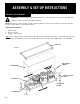
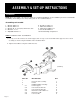
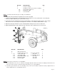
STEP 7: Install the engine / pump assembly. See FIGURE 9.
1. Insert vibration isolator each between the engine and the mount plate at the four mounting hole positions.
2. Secure the engine with the M8 hardware, then tighten the harware using two 13mm wrenches.
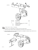
REF. NO. DECSRIPTION QTY.
12
Engine / Pump assembly
1
13
Hardware kit # 5-1, including:
1
13-1
Hex head bolt / M8 x 40
4
13-2
Flat washer / M8
8
13-3
Lock nut / M8
4
13-4
Vibration isolator / Ø9
4
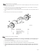
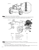
STEP 8: Attach the oil suction hose and Pump / Valve connecting hose. See FIGURE 10.
The two hydraulic hoses listed below, each of them has one end fixed on the log splitter by manufacturer, the other open
end needs to be attached.
1. Oil suction hose ¾”, labeled as ①, comes from the bottom of the reservoir.
Loosen the hose clamp on the open end of this hose using a flat head screwdriver, and then connect the hose to the
fitting on the bottom of the pump, which is labeled of a same ①. Tighten the hose clamp.
(FIGURE 9)
Page 17
(FIGURE 8)