
Full Product Manual


Page 21
Regular maintenance is the way to ensure the best performance and long life of your machine. Please refer to this manual
and the engine manufacturer’s owner’s manual for maintenance procedures.
WARNING! Do not make any adjustments without first stopping the engine, disconnecting the
spark plug wire and grounding it against the engine. Always wear safety glasses during operation
or while performing any adjustments or repairs.
Engine
Refer to the Engine Operator’s manual packed with your log splitter for all engine maintenance e.g. how to check and
change the engine oil.
NOTE: When draining oil from the engine on this log splitter, shield the hoses from any oil that may run down the frame
and drip onto the hoses. Thoroughly wipe any residual oil off the log splitter and hoses after completing service.
Tire Pressure
The tires coming with your log splitter are pneumatic off-road tires. The max recommended operating pressure is 30 psi. Do
not, under any circumstances, exceed the manufacturer’s recommended psi. Maintain equal pressure on all tires.
WARNING! Excessive pressure when seating beads may cause the tire/rim assembly to burst with
force sufficient to cause serious injury.
Flexible Pump Coupler
The flexible pump coupler, located between the pump and the engine shaft, has a nylon “spider” insert. Over time, the insert
will harden and deteriorate. If you detect vibration or noise coming from the area between the engine and the pump contact
an authorized dealer or Boss Industrial, Inc. Change a new coupler spider immediately, if the coupler fails completely, you
will experience a loss of hydraulic power.
Hydraulic Fluid
Check the hydraulic fluid level in the log splitter reservoir tank before each use. Maintain the fluid level within the range
specified on the dipstick at all times.
Change the hydraulic fluid in the reservoir every 100 hours of operation. Follow the steps below:
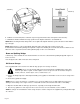
1. Place a suitable oil collection container under the tank.
2. Disconnect the oil drain screw from the bottom of the reservoir tank. See FIGURE 17.
4. Allow the fluid to drain into the container.
NOTE: The reservoir tank has a capacity of 4 gallons of hydraulic fluid.
5. After draining, screw on the oil drain screw and tighten.
MAINTENANCE & ADJUSTMENTS
Page 24