CONTENTS Installation...................................................................................................................3 DIN Front-Mount (Method A)........................................................................................3 Installing the unit ...................................................................................................3 Removing the unit..................................................................................................
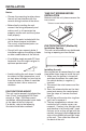
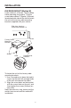
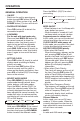
INSTALLATION Notes: TAKE OUT SCREWS BEFORE INSTALLATION • Choose the mounting location where the unit will not interfere with the normal driving function of the driver. Before install the unit, please remove the two screws. Take out screw before installation • Before finally installing the unit, connect the wiring temporarily and make sure it is all connected up properly and the unit and the system work properly. • Use only the parts included with the unit to ensure proper installation.
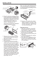
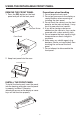
INSTALLATION Note: to install the short threading terminal of the mounting bolt to the back of the unit and the other long threading terminal to the dashboard. Sleeve L Key Outer Trim Ring Front Panel Spring Washer Hex Nut Metal Strap Mounting Bolt Plain Washer R Key Tapping Screw 6. Mount the sleeve by inserting the sleeve into the opening of the dashboard and bend open the tabs located around the sleeve with a screwdriver.
INSTALLATION DIN REAR-MOUNT (Method B) If your vehicle is a Nissan, Toyota, follow these mounting instructions. Use the screw holes marked T (Toyota), N (Nissan) located on both sides of the unit to fasten the unit to the factory radio mounting brackets supplied with your vehicle. Side view showing Screw Holes marked T, N Screw Factory Radio Mounting Bracket Hook Screw Hook Dashboard or Console To fasten the unit to the factory radio mounting brackets. 1.
USING THE DETACHABLE FRONT PANEL REMOVE THE FRONT PANEL Precautions when Handling 1. Press the REL button on the front panel and pull off the front panel. 1. Do not drop the front panel. 2. Do not put pressure on the display or control buttons when removing or installing the front panel. 3. Do not touch the contacts on the front panel or on the main unit body. It may result in poor electrical contact. 4.
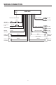
WIRING CONNECTION MAIN UNIT (BLACK) ANTENNA CONNECTOR Rch RED AUX IN CABLE Lch WHITE FUSE RED IGNITION SWITCH (ACC+) Constant 12 volts YELLOW FUSE FRONT RCA CABLE (BROWN) Rch RED BLACK GROUND (B–) Lch WHITE (GREY) POWER ANTENNA FRONT Lch SPEAKER REAR Lch SPEAKER REAR RCA CABLE BLUE Rch RED Lch WHITE WHITE GREY WHITE/BLACK GREY/BLACK GREEN VIOLET GREEN/BLACK VIOLET/BLACK 7 FRONT Rch SPEAKER REAR Rch SPEAKER
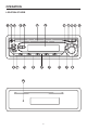
OPERATION LOCATION OF KEYS 20 1 3 21 7 12 13 8 5 14 19 15 17 16 22 8 2 4 9 6 18 11 10
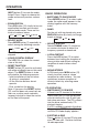
OPERATION Press the VOL+/- (20)(21) to select your setting. GENERAL OPERATION • ON/OFF Switch on the unit by pressing any button (except REL button (6) and button (4)). When system is on, press POWER button (1) to turn off the unit. BEEP ON/OFF 12hours/24hours • LOUDNESS For the unit with two bands only: Press and hold BND/LOU button (8) for several seconds to show the loudness state. And shortly press it again to turn on/off the subwoofer output.
OPERATION (MUT) button (2) to mute the audio output. Press it again to release this mode and recover previous volume level. RADIO OPERATION • SWITCHING TO RADIO MODE Press MODE button (7) to select radio mode, the radio mode appears in the display together with the memory band. • EQUALIZATION Press EQ button (10) shortly to turn on equalization function and to select desired audio mode.
OPERATION • PAUSING CD Press button (2) shortly to pause CD player. Press it shortly again to resume playback. DISC NOTES: A. Notes on discs: 1. Attempting to use nonstandard shape discs (e.g. square, start, heart) may damage the unit. Be sure to use round shape CD discs only for this unit. 2. Do not stick paper or tape etc., onto the label side or the recording side of any discs, as it may cause a malfunction. 3. Dirt, dust, scratches and warping discs will cause misoperation.
SPECIFICATION GENERAL Power Supply Requirements Chassis Dimensions Tone Controls - Bass (at 100 Hz) - Treble (at 10 KHz) Maximum Output Power Current Drain : DC 12 Volts, Negative Ground : 178 (W) x 163 (D) x 50 (H)mm : : : : ± 7dB ± 7 dB 40W x 4 (ch) 15 Amps. (max.) CD PLAYER Signal to Noise Ratio Channel Separation Frequency Response : More than 55 dB : More than 40 dB : 50 Hz - 15 KHz RADIO FM 88 to 108 MHz 10.
TROUBLE SHOOTING Before going through the checklist, check wiring connection. If any of the problems persist after check list has been made, consult your nearest service dealer. Symptom No power. Disc cannot be loaded or ejected. Cause Solution The car ignition switch is not on. If the power supply is connected to the car accessory circuits, but the engine is not moving, switch the ignition key to “ACC”. The fuse is blown. Replace the fuse. Presence of CD disc inside the player.