
Service manual


11
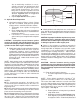
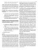
due to machining variations in cases,
cylinders or pistons, top land of piston deck
will appear closer to cylinder wall at one
point around circumference. This means
that piston is cocked in cylinder bore and
can be corrected by bending rod in opposite
direction. Figure 5 shows an exaggerated
side view of this condition.
5. Repeat Steps B to D for other cylinder.
11. Cylinder Head Preparation
A. Head Gasket Surface Flatness Check - Before
top end is assembled, head gasket to cylinder
mating surfaces should be checked as follows
1. Thoroughly clean cylinder head gasket
surfaces.
2. Place straight edge ruler across head gasket
surface at different places around diameter
to determine flatness.
3. If unevenness is revealed, machine head
gasket surface just enough to make complete
contact.
CAUTION - Incomplete contact between gasket
surfaces of cylinders and cylinder heads may cause
combustion leakage possibly resulting in damage to
cylinders and/or other engine components.
B. Modify 883 Cylinder Head Combustion Chamber
- If 883cc cylinder heads are to be used, the
combustion chambers must be modified to
improve air flow and reduce the compression ratio.
Follow enclosed Instruction Sheet #3883 or #3884
depending on style of combustion chambers in
heads to be used. 1200cc heads do not require
this modification.
NOTE - Stock 1200cc heads or modified 883 heads will
provide a usable compression ratio but the small valves
and ports in stock heads will be a limiting factor for a large
displacement performance motor. To achieve the full
potential of the engine it is recommended that the size of
the valves be increased and the ports modified to further
improve flow. In weighing the expense and difficulty of
these modifications, it may be more cost effective and
results intensive to use S&S or other aftermarket
performance heads.
12. Piston to Head & Piston to Valve Clearancing
NOTES
●
The clearancing operations described in this
section can be done simultaneously as the same set-
ups are used. Please read this entire section before
beginning work.
●
All valve spring spacing, rocker arm to collar and rocker
arm to rocker cover clearancing must be done before
piston to valve clearancing can be checked.
●
S&S flat topped pistons have sufficient valve clearance
when used with most street high performance cams with
lifts up to .525". However, we recommend that valve
clearancing be checked if other than stock cam is used.
●
If S&S cylinder heads and pistons are used, cams of
up to .560" lift can be run without valve to piston clearance
problems. If cams with higher lift are used this clearance
must be checked.
CAUTION - Improper installation of pistons may cause
unwarranted stress, premature wear and/or contact
with each other or other engine components resulting
in damage to pistons or other engine parts.
●
If there is any resistance or contact at any point in
rotation it must be diagnosed and corrected. Since it is
nearly impossible to anticipate every possible engine
combination, it is the engine builder’s responsibility to
check for proper running clearances. S&S considers
checking and establishing all running clearances as
standard engine building practice that must be performed
during engine assembly. Engine failure due to improper
clearances between moving parts is not covered under
warranty.
CAUTION - Contact between moving engine
components may cause damage or destruction of the
parts involved and produce abrasive particles which
may cause damage or premature wear to other engine
components.
A. Piston to head (squish) clearance
1. Assemble engine with exception of cylinder
heads.
NOTE - Pinion Shafts included in all S&S V
2
XL
flywheels kits and assemblies are of the 1987 type.
This means that 1986 crankcases must be converted
to use the 1987 and later style caged roller pinion main
bearing assembly, and that 1986 -1987 style pinion gear
and oil pump drive gears must be used in 1988 and
later engines. See step 6.
2. Rotate flywheels so front piston is positioned
at top dead center.
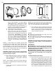
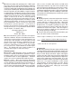
3. Note where piston deck (See Figure 6, piston
deck diagram) is positioned in relationship to
head gasket surface. Piston deck (flat located
Figure 6
Deck Height
Piston Deck
Wrist Pin Hole