
Operator`s manual


OVERHAUL
MANUAL-
LYCOMING
DIRECT
DRIVE
AIRCRAFT
ENGINES
Section 1
Introduction
SECTION
1.
INTRODUCTION
1-1.
This
manual
contains
the
necessary
information
for
the major
overhaul
of
the Avco
Lycoming
horizon-
tally
installed
direct
drive
engines.
Unless
otherwise
noted,
all information
and data
in
the manual
will ap-
ply
equally
to
all models;
those
portions
of
the text
ap-
plying
to
any one
particular
model
or
series
will
be so
identified.
1-2.
The main
portion
of the
text
is divided
into sec-
tions
corresponding
to
the
basic
engine
components.
Additional
sections
are
provided
for
general
descrip-
tion,
general
overhaul
and
inspection
procedures,
pre-
servation
and
storage
information,
and
other
items
of
a
non-specific
nature.
1-3.
The
tools
required
for overhauling
the
engines
(excludingthe
ordinary
mechanic's
tools
found
inmost
overhaulshops)
are
listed
inSSP-2172
SpecialService
Tools.
Inspection
gages
are
also
listed
in
the same
section.
Any special
information
required
concerning
these
tools
may
be obtained
by
writing
to the
Service
Department,
Avco
Lycoming
Division,
Williamsport,
Pennsylvania,
17701.
When
requesting
information
concerninganyofthesetools,
refer
to
thetool
by name
and
part number
and not
merely
by
name.
1-4.
Parts
catalogs,
for
specific
models,
may
be
or-
dered
from
the
department
listed
in
paragraph
1-3.
Because
this
manual
covers
the
entire
series
of
en-
gines,
it
is almost
impossible
to call
out attaching
parts
for
specific
models.
Therefore,
it
is recom-
mended
that
the
parts
catalogs
be
used
in
conjunction
with
the
manual,
when
reassembling
the
engine.
1-5.
Service
bulletins,
service
instructions
and
service
letters
are
issued
from
time
totime
whenever
the
en-
gine
is modified
or overhaul
procedures
revised.
When
received,
these
publications
should
be
inserted
in
the
rear
of this
manual
or
maintained
in a separate
file
for
ready
reference.
1-6.
The followingprocedure
should
be
followed
if,
for
any
reason,
parts
are to
be
returned
to
the factory.
You
may
obtain
from,
but preferably
have
your
dis-
tributor
complete,
the
applicable
warranty
or
rework
form.
These
forms
must
include
the
engine
model
and
serial
numbers,
number
of hours
in
service,
the
reason
for the
parts
being
returned
and
any
other
pertinent
facts
concerning
the
parts.
1-7.
In
this
manualall
references
to
locations
of var-
ious
components
will
be designated
when
viewing
the
engine
from
the
rear.
The
power
take
off
end
is
con-
sideredthe
front
and
the
accessory
drive
end
the
rear.
The
oil
sump
is
considered
the
bottom.
Cylinders
are
numbered
from
front
to
rear
with
odd
numbered
cyl-
inders
on
the
right
side.
1-8.
The
direction
of rotation
of
the
crankshaft,
as
viewed
from
the rear,
is
clockwise
on all
models
with
the
following
exception.
The
direction
of
rotation
of
the
crankshaft,
as
viewed
from
the
rear
is
counter-
clockwise
on
all
models
withthe
letter
L in
the
model
prefix.
(Example
- LIO-320-B1A).
All
references
to
direction
of rotation
of
the
various
accessory
drives
are
as
viewed
facing
the
accessory
drive
mounting
pad.
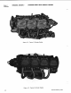
Figure
1-1.
Typical
4 Cylinder
Engine
Revised
October
1974
1-1