GT-42 4-Channel, High-Current/High-Power Amplifier
Table of Contents Parts List Features and Specifications Control Functions 3 3 4 Control functions (cont.) Control functions (cont.) 5 6 Mechanical Functions 6 Control cover removal and reinstallation Multi-position mounting feet Mechanical functions (cont.) Amplifier linking Wire connection Fuses General Installation Precautions Before you install Battery and charging system Wire routing Installation—Amplifier Mounting Choose the mounting location Installation—amplifier mounting (cont.
Parts List Included Hardware (1) owner’s manual (1) female quick-connect terminal for remote input (1) 2mm hex wrench (for speaker input) (1) 3mm hex wrench (for power input) (6) mounting screws Features and Specifications GT-42 Features 4-Channel, High-Current Amplifier 2Ω Bridge Stable (Mono) Operation Power Increase with Input Voltage Rise Advanced Cooling Allows Varied Mounting Positions Adjustable Feet for Varied Mounting Surfaces Security Cover Protects Control Settings 24dB or 12dB Octave Lowpass Se
Control Functions 5 3 STEREO SEND I N P UT REAR 9 OFF ON REAR INPUT 350 200 12 MONO STEREO HIGHPASS FRONT INPUT O FF 10 ON SU B WO O FER LEVEL L 20 OFF ON FUSE 3 x 25 A LOWPASS 12dB 12dB 24dB MONO ST 6 Hz LOWPA SS SLO PE 350 200 Hz 50 MONO 0.2 I N P U T S E N S I T I VI TY 2 .6 V 1.2 0 .9 5 5 0.2 INPUT SENSITIVITY Q/HP SUBWOOFER LEVEL FRONT SPEAKER OUTPUT 4 11 R B+ B+ GND GND 5 REMOTE 4 2 MONO L R L V 0 .7 REMOTE 1 2.6 REAR SPEAKER OUTPUT 1 2 .
Control Functions (cont.) 6 “Q” Control “Q” Control is active when the highpass crossover is engaged and is centered on the selected crossover point. The range of operation is 0.7–1.2. dB Q +1.6dB 0dB -3dB .707 .95 1.2 t (tuned crossover frequency) 7 REAR RCA Inputs RCA cables marked “REAR” from head unit or other line level device should be connected here. Use both inputs (L & R) for stereo.
Control Functions (cont.) 12 Subwoofer Level Control and Port Switch should be set to “OFF” when control circuit is not installed, (see optional “subwoofer level control” owner’s manual). cover panel Mechanical Functions Recessed RCA Inputs The input jacks are recessed into the body of the amplifier to provide clearance in tight mounting locations. 1 inch 1 inch Control Cover Removal and Reinstallation The cover panel is secured with two (2) captive coin-slotted screws.
Mechanical Functions (cont.) Amplifier Linking The design of the side panels enables multiple amplifiers to be used together without additional hardware. GT-42 GT-20 Wire Connection Amplifier accepts stripped wire directly into the terminal blocks. Speaker outputs accept 8-gauge, and the DC power and ground accept 4-gauge. Tighten with supplied hex wrenches. Fuses Amplifier accepts standard AT-style automotive blade fuses.
General Installation Precautions WARNING! Before driving the amplifier mounting screws through any surface, be sure of what is behind that surface. Check for the gas tank, brake lines, and any vehicle wiring harness. Never run wires outside or under the vehicle or where they could become broken or interfere with the safe operation of the vehicle. Before You Install Before you install the unit, disconnect the negative (–) battery cable in the engine compartment of the vehicle.
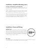
Installation—Amplifier Mounting Choose the Mounting Location Plan your installation so that the amplifier is mounted where adequate ventilation is available. Never mount an amplifier in the engine compartment of a vehicle! WARNING! Before driving the mounting screws through any surface, be sure of what is behind that surface. Check for gas tank, brake lines, and any vehicle wiring harness. 13mm (1/2”) 225mm (87/8”) GT-42 S TATUS MONO 12.6–14.
Installation—Amplifier Mounting (cont.) Passenger and Trunk Compartment Mounting If the amplifier is mounted under a seat, be sure that the vents do not become blocked. Do not allow seat padding or other obstructive material to press down on the amplifier. All Boston GT amplifiers have top panel controls. If the amplifier is mounted under a seat, position the amplifier so the cover panel can be removed with the seat forward or back to allow adjustment of the audio settings.
Installation—Fuses and Wiring (cont.) Power/B+ and Power/GND Connection Strip approximately 5/8" (16mm) of insulation. The positive (+) power wire is installed into the amplifier terminal marked “B+.” The negative (–) wire is installed into the terminal marked “GND.” The ground wire should be as short as possible and connected directly to the chassis of the vehicle.
Installation—Fuses and Wiring (cont.) Mono Subwoofer Operation If the amplifier is to be bridged and used with a subwoofer connected to the REAR channels, use the “SPEAKER OUTPUT” terminals marked for mono use. WARNING! Subwoofer impedance must not fall below 2 ohms when in MONO mode. 2-ohm minimum Setup Tuning—Full-Range Speakers 1) Music The material chosen for head unit/amplifier system setup must be both clear in recording quality and dynamic in amplitude.
Setup Tuning—Full-Range Speakers (cont.) 4) Head Unit The head unit should have all controls such as bass, treble, balance, and fader set to the flat or centered position. The volume control should be at the minimum setting. If the head unit has any equalization or bass management features such as boost, they should be defeated at this time. Turn head unit on, and verify that the GREEN status LED is lit on the amplifier.
Setup Tuning—Full-Range Speakers (cont.) 8) FRONT “Q” Control Once the FRONT highpass crossover point has been determined, use the FRONT “Q” control to increase the bass information centered around the crossover point. Setting the front “Q” control is done in conjunction with setting the levels on the input sensitivity and highpass crossover frequency controls.
Setup Tuning—Subwoofers (cont.) 3) Head Unit The head unit should have all controls such as bass, treble, balance, and fader set to the flat or centered position. The volume control should be at the minimum setting. If the head unit has any equalization or bass management features such as boost, they should be deactivated at this time. Turn head unit on, and verify that the GREEN status LED is lit on the amplifier.
System Examples 6.5LF System A—Full-Range Front with Full-Range Rear 6.5LF to ground to ground fuse to to + battery terminal + battery terminal 6.5LF fuse 6.5LF 6.5LF System B—Full-Range Front with Rear Fill 6.5LF to ground to ground fuse to to + battery terminal + battery terminal 6.5LF fuse 6.
System Examples (cont.) 6.5LF System C—Main Speakers with Single Subwoofer (2Ω) 6.5LF to ground to ground fuse to fuse to + battery terminal + battery terminal 2Ω 10.5LF 6.5LF System D —Main Speakers with Parallel 4Ω Subwoofers (2Ω load) 6.5LF to ground to ground fuse fuse 6.5LF to to + battery terminal + battery terminal 6.
Amplifier Troubleshooting Guide Status LEDs on Amplifier not Lit—Head Unit (Source) Turned “ON” Verify Remote turn-on wire from source to amplifier has proper voltage Power (B+) connections at amplifier, terminal blocks, and battery are secure Ground (GND) connections at amplifier and vehicle chassis are secure Battery B+ fuse is OK Amplifier fuse is OK B+ at battery and B+ at amplifier have proper voltage Status LEDs Lit, no Output from Speakers—Speakers in Normal Operating Condition Verify High-level c
Contact and Warranty Information Limited Warranty (US) For one (1) year from the date of purchase, Boston Acoustics will repair for the original owner any defect in materials or workmanship that occurs in normal use, without charge for parts and labor—when purchased from an authorized Boston Acoustics retailer. If an authorized Boston Acoustics retailer installs your amplifier, the warranty will be extended one (1) additional year.