
Installation Guide


ASSEMBLY INSTRUCTIONS
HARDWARE USED
Wood Dowel x22
Cam Bolt x22
Cam Lock x22
Paper Cover x22
HARDWARE USED
Screw 1/2” x 4
Magnet x 2
12
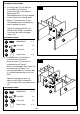
15. Insert cam locks (3) into holes on
assembled parts from Figure 12.
Screw cam bolts (2) into holes on left
side panel (C).
Attach left side panel (C) to assembled
unit on Figure 12 by inserting wood
dowels (1) and cam bolts (2) into
corresponding holes.
Tighten by rotating cam locks (3)
clockwise with Phillips screwdriver.
Repeat steps to attach right side panel
(D). Cover cam lock holes with paper
covers (16).
This step may take two people to
complete.
Work panels (C) and (D) from bottom to
top assuring that all cam bolts and
wood dowels are inserted through their
corresponding holes.
16. Attach magnets (7) to top panel (A) with
screws (6).
Tighten screws with Phillips
screwdriver.
16
1
2
3
16
15
1
2
C
D
B
16
6
7
A
7
6