
Installation Guide


ASSEMBLY INSTRUCTIONS
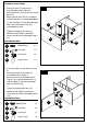
HARDWARE USED
Wood Dowel x 8
Cam Bolt x 8
Cam Lock x 8
Paper Cover x 8
HARDWARE USED
Wood Dowel x 8
Cam Bolt x 8
Cam Lock x 8
Paper Cover x 8
7
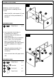
5. Insert cam locks (3) into corresponding
holes on vertical panels (J). Screw cam
bolts (2) into corresponding holes on
assembled unit on Figure 3.
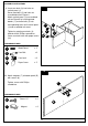
Attach assembled unit to vertical panels
(J) by inserting wood dowels (1) and
cam bolts (2) into corresponding holes
until vertical panel (J) and assembled
unit meet.
Tighten by rotating cam locks (3)
clockwise with Phillips screwdriver.
Cover cam lock holes with paper covers
(16).
Repeat these steps to attach shelf (K) to
assembled parts.
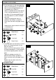
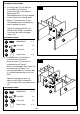
6. Insert cam locks (3) into holes on vertical
panels (G). Screw cam bolts (2) into
holes on shelf (F).
Attach shelf (F) to vertical panels (G) by
inserting wood dowels (1) and cam bolts
(2) into corresponding holes until they
meet.
Tighten by rotating cam locks (3)
clockwise with Phillips screwdriver.
Cover cam lock holes with paper covers
(16).
Repeat steps to attach shelf (E) to
vertical panel
s (G).
5
6
1
2
3
16
1
2
3
16
K
J
J
1
2
3
16
F
1
2
G
G
E
3
16
16