Page 1 of 43 TEST REPORT IEC 60950-1 Information technology equipment – Safety – Part 1: General requirements Report Number. ..............................: 68.210.18.0104.01 Date of issue ...................................: 2018-05-08 Total number of pages ...................: 43 Applicant’s name ............................: GZTOD.CO.,LTD Address ...........................................
Page 3 of 43 Report Ref. No.: 68.210.18.0104.01 Test item particulars...................................................: Equipment mobility.................................................: [X] movable [] stationary [] hand-held [] transportable [] for building-in [] direct plug-in Connection to the mains........................................
Page 4 of 43 Report Ref. No.: 68.210.18.0104.01 General remarks: "(See Enclosure #)" refers to additional information appended to the report. "(See appended table)" refers to a table appended to the report. Throughout this report a comma / point is used as the decimal separator. Manufacturer’s Declaration per sub-clause 4.2.
Page 5 of 43 Report Ref. No.: 68.210.18.0104.01 IEC 60950-1 Clause Requirement + Test Result - Remark 1 GENERAL P 1.5 Components P 1.5.1 General P Comply with IEC 60950-1 or relevant component standard (see appended tables 1.5.1) Verdict P 1.5.2 Evaluation and testing of components P 1.5.3 Thermal controls No thermal controls 1.5.4 Transformers See Annex C 1.5.5 Interconnecting cables 1.5.6 Capacitors bridging insulation 1.5.7 Resistors bridging insulation 1.5.7.
Page 6 of 43 Report Ref. No.: 68.210.18.0104.01 IEC 60950-1 Clause Requirement + Test Result - Remark Multiple mains supply connections.........................: Only one mains supply connection Rated voltage(s) or voltage range(s) (V) ...............: 100-240V Symbol for nature of supply, for d.c. only ...............: 1.7.1.2 Verdict N/A P N/A Rated frequency or rated frequency range (Hz) ....: 50/60Hz P Rated current (mA or A) ........................................: 1.
Page 7 of 43 Report Ref. No.: 68.210.18.0104.01 IEC 60950-1 Clause Requirement + Test Result - Remark Verdict 1.7.8.4 Markings using figures ..........................................: 1.7.9 Isolation of multiple power sources ........................: Single power source only N/A 1.7.10 Thermostats and other regulating devices .............: No such regulating devices N/A 1.7.11 Durability 1.7.12 Removable parts 1.7.13 Replaceable batteries ..........................................
Page 8 of 43 Report Ref. No.: 68.210.18.0104.01 IEC 60950-1 Clause Requirement + Test Result - Remark Verdict 2.2.2 Voltages under normal conditions (V) .................. : Within SELV limits P 2.2.3 Voltages under fault conditions (V) ....................... : Within SELV limits P 2.2.4 Connection of SELV circuits to other circuits .......: Connect to SELV circuits only P 2.3 TNV circuits 2.3.1 Limits N/A No TNV circuits N/A Type of TNV circuits ......................................
Page 9 of 43 Report Ref. No.: 68.210.18.0104.01 IEC 60950-1 Clause Requirement + Test Result - Remark Verdict Use of integrated circuit (IC) current limiters N/A d) Overcurrent protective device limited output N/A Max. output voltage (V), max. output current (A), max. apparent power (VA) ..................................... : Current rating of overcurrent protective device (A) .: 2.6 Provisions for earthing and bonding N/A 2.6.1 Protective earthing 2.6.
Page 10 of 43 Report Ref. No.: 68.210.18.0104.01 IEC 60950-1 Clause Requirement + Test Result - Remark 2.6.5.6 Corrosion resistance N/A 2.6.5.7 Screws for protective bonding N/A 2.6.5.8 Reliance on telecommunication network or cable distribution system N/A 2.7 Overcurrent and earth fault protection in primary circuits 2.7.1 Basic requirements Fuse “F1” integrated part of the equipment Verdict P P Instructions when protection relies on building installation N/A 2.7.
Page 11 of 43 Report Ref. No.: 68.210.18.0104.01 IEC 60950-1 Clause Requirement + Test Result - Remark 2.9.3 Grade of insulation Functional, basic, supplementary, double or reinforced insulation 2.9.4 Separation from hazardous voltages Verdict P P Method(s) used ..................................................... : Method 1 2.10 Clearances, creepage distances and distances through insulation P 2.10.1 General P 2.10.1.1 Frequency ......................................................
Page 12 of 43 Report Ref. No.: 68.210.18.0104.01 IEC 60950-1 Clause Requirement + Test Result - Remark Verdict For a d.c. mains supply ......................................... : N/A b) Transients from a telecommunication network : N/A 2.10.4 Creepage distances P 2.10.4.1 General P 2.10.4.2 Material group and comparative tracking index P CTI tests................................................................. : Material group IIIb was assumed for others. 2.10.4.
Page 13 of 43 Report Ref. No.: 68.210.18.0104.01 IEC 60950-1 Clause Requirement + Test Result - Remark Verdict 2.10.5.14 Additional insulation in wound components N/A Working voltage .................................................... : N/A - Basic insulation not under stress ........................ : N/A - Supplementary, reinforced insulation ................. : N/A 2.10.6 Construction of printed boards P 2.10.6.1 Uncoated printed boards 2.10.6.2 Coated printed boards N/A 2.10.6.
Page 14 of 43 Report Ref. No.: 68.210.18.0104.01 IEC 60950-1 Clause Requirement + Test Result - Remark Verdict 3.1.9 Termination of conductors P 10 N pull test P 3.1.10 Sleeving on wiring N/A 3.2 Connection to a mains supply 3.2.1 Means of connection 3.2.1.1 Connection to an a.c. mains supply P 3.2.1.2 Connection to a d.c. mains supply N/A 3.2.2 Multiple supply connections N/A 3.2.
Page 15 of 43 Report Ref. No.: 68.210.18.0104.01 IEC 60950-1 Clause Requirement + Test Result - Remark Rated current (A), cord/cable type, cross-sectional area (mm2) ............................................................. : 3.3.5 Verdict Wiring terminal sizes N/A Rated current (A), type, nominal thread diameter (mm) ..................................................................... : 3.3.6 Wiring terminal design N/A 3.3.7 Grouping of wiring terminals N/A 3.3.
Page 16 of 43 Report Ref. No.: 68.210.18.0104.01 IEC 60950-1 Clause Requirement + Test Result - Remark Rack-mounted equipment. Verdict N/A 4.2.2 Steady force test, 10 N P 4.2.3 Steady force test, 30 N N/A 4.2.4 Steady force test, 250 N P 4.2.5 Impact test N/A Fall test N/A Swing test N/A 4.2.6 Drop test; height (mm) ........................................... : 1000 P 4.2.7 Stress relief test 107.0ºC, 7h P 4.2.
Page 17 of 43 Report Ref. No.: 68.210.18.0104.01 IEC 60950-1 Clause Requirement + Test Result - Remark Verdict Flash point (C) .....................................................: N/A 4.3.13 Radiation N/A 4.3.13.1 General N/A 4.3.13.2 Ionizing radiation N/A 4.3.13.3 Measured radiation (pA/kg) ..................................: Measured high-voltage (kV) .................................: Measured focus voltage (kV) ................................: CRT markings ..............
Page 18 of 43 Report Ref. No.: 68.210.18.0104.01 IEC 60950-1 Clause Requirement + Test Result - Remark Verdict 4.5.1 General P 4.5.2 Temperature tests P Normal load condition per Annex L ......................: (see appended table 4.5) 4.5.3 Temperature limits for materials (see appended table 4.5) P 4.5.4 Touch temperature limits (see appended table 4.5) P 4.5.5 Resistance to abnormal heat ................................: N/A 4.6 Openings in enclosures N/A 4.6.
Page 19 of 43 Report Ref. No.: 68.210.18.0104.01 IEC 60950-1 Clause Requirement + Test Result - Remark 4.7.3.5 Materials for air filter assemblies N/A 4.7.3.6 Materials used in high-voltage components N/A 5 ELECTRICAL REQUIREMENTS AND SIMULATED ABNORMAL CONDITIONS P 5.1 Touch current and protective conductor current P 5.1.1 General 5.1.2 Configuration of equipment under test (EUT) N/A 5.1.2.1 Single connection to an a.c. mains supply N/A 5.1.2.
Page 20 of 43 Report Ref. No.: 68.210.18.0104.01 IEC 60950-1 Clause Requirement + Test Result - Remark Verdict 5.2 Electric strength 5.2.1 General (see appended table 5.2) P 5.2.2 Test procedure (see appended table 5.2) P 5.3 Abnormal operating and fault conditions 5.3.1 Protection against overload and abnormal operation (see appended table 5.3) 5.3.2 Motors No motor 5.3.3 Transformers (see appended Annex C) P 5.3.4 Functional insulation ...........................................
Page 21 of 43 Report Ref. No.: 68.210.18.0104.01 IEC 60950-1 Clause Requirement + Test Result - Remark Current limiting method ........................................ : Verdict 7 CONNECTION TO CABLE DISTRIBUTION SYSTEMS N/A 7.1 General N/A 7.2 Protection of cable distribution system service persons, and users of other equipment connected to the system, from hazardous voltages in the equipment N/A 7.3 Protection of equipment users from overvoltages on the cable distribution system N/A 7.
Page 22 of 43 Report Ref. No.: 68.210.18.0104.01 IEC 60950-1 Clause Requirement + Test Result - Remark Flame A, B or C .................................................... : Verdict A.2.5 Test procedure N/A A.2.6 Compliance criteria N/A A.2.7 Sample 1 burning time (s) ..................................... : Sample 2 burning time (s) ..................................... : Sample 3 burning time (s) ..................................... : Alternative test acc. to IEC 60695-11-5, cl.
Page 23 of 43 Report Ref. No.: 68.210.18.0104.01 IEC 60950-1 Clause Requirement + Test B.7.1 General N/A B.7.2 Test procedure N/A B.7.3 Alternative test procedure N/A B.7.4 Electric strength test; test voltage (V) ................. : N/A B.8 Test for motors with capacitors N/A B.9 Test for three-phase motors N/A B.10 Test for series motors N/A C Result - Remark Verdict Operating voltage (V) ........................................... : ANNEX C, TRANSFORMERS (see 1.5.4 and 5.3.
Page 24 of 43 Report Ref. No.: 68.210.18.0104.01 IEC 60950-1 Clause Requirement + Test Result - Remark G.2.1 AC mains supply .................................................. : N/A G.2.2 Earthed d.c. mains supplies ................................. : N/A G.2.3 Unearthed d.c. mains supplies ............................. : N/A G.2.4 Battery operation .................................................. : N/A G.3 Determination of telecommunication network transient voltage (V) ..................
Page 25 of 43 Report Ref. No.: 68.210.18.0104.01 IEC 60950-1 Clause Requirement + Test Result - Remark Verdict L.3 Erasers N/A L.4 Pencil sharpeners N/A L.5 Duplicators and copy machines N/A L.6 Motor-operated files N/A L.7 Other business equipment M ANNEX M, CRITERIA FOR TELEPHONE RINGING SIGNALS (see 2.3.1) N/A M.1 Introduction N/A M.2 Method A N/A M.3 Method B N/A M.3.1 Ringing signal N/A M.3.1.1 Frequency (Hz) ....................................................
Page 26 of 43 Report Ref. No.: 68.210.18.0104.01 IEC 60950-1 Clause Requirement + Test Result - Remark Verdict R ANNEX R, EXAMPLES OF REQUIREMENTS FOR QUALITY CONTROL PROGRAMMES N/A R.1 Minimum separation distances for unpopulated coated printed boards (see 2.10.6.2) N/A R.2 Reduced clearances (see 2.10.3) N/A S ANNEX S, PROCEDURE FOR IMPULSE TESTING (see 6.2.2.3) N/A S.1 Test equipment N/A S.2 Test procedure N/A S.
Page 27 of 43 Report Ref. No.: 68.210.18.0104.01 IEC 60950-1 Clause Requirement + Test Y ANNEX Y, ULTRAVIOLET LIGHT CONDITIONING TEST (see 4.3.13.3) N/A Y.1 Test apparatus ..................................................... : N/A Y.2 Mounting of test samples ..................................... : N/A Y.3 Carbon-arc light-exposure apparatus .................. : N/A Y.4 Xenon-arc light exposure apparatus .................... : N/A Z ANNEX Z, OVERVOLTAGE CATEGORIES (see 2.10.3.
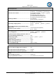
Page 28 of 43 Report Ref. No.: 68.210.18.0104.01 IEC 60950-1 Clause Requirement + Test 1.5.1 TABLE: List of critical components Object/part No. Plastic enclosure Appliance inlet Result - Remark Manufacturer/ trademark SABIC INNOVATIVE PLASTICS B V DONGGUAN HUACONN ELECTRONICS CO LTD Type/model 940(f1) HC-88 P Technical data Standard (Edition Mark(s) of / year) conformity1) UL PC, V-0, 120C, UL 94 min. 1.5mm thickness AC 250V, 2.5A, IEC/EN 60320-1 VDE, UL 70C UL 60320-1 CSA-C22.2 No. 60320-1 T2.
Page 29 of 43 Report Ref. No.: 68.210.18.0104.01 IEC 60950-1 Clause Requirement + Test Result - Remark Optocoupler (U2) Everlight Electronics Co., Ltd. EL817 (Alternative) Lite-On Technology Corporation LTV-817 (Alternative) Bright Led Electronics Corp.
Page 30 of 43 Report Ref. No.: 68.210.18.0104.01 IEC 60950-1 Clause Requirement + Test Line filter (LF1) Result - Remark T12.7*7.9*6.3523MH Min. 130°C, 25MH -Magnet wire Shenzhen Changpingsheng Electronics Co., Limited Interchangeable Interchangeable Min. 130C -PCB Interchangeable Interchangeable Transformer (T1) SHENZHEN HUA ZHI CHUANG ELECTRONIC TECHNOLOGY CO LTD Sumitomo Bakelite PM-9820, PMCo Ltd 9630 -Bobbin -Magnet wire (Alternative) IEC 60950-1 UL 60950-1 CAN/CSA-C22.2 No.
Page 31 of 43 Report Ref. No.: 68.210.18.0104.01 IEC 60950-1 Clause Requirement + Test Result - Remark 1.5.1 TABLE: Opto Electronic Devices Manufacturer: Type: Separately tested: Bridging insulation: Verdict P Everlight Lite-On LTV-817 Bright Led BPC-817C ORIENT ORPC-817C EL817 UL, VDE UL, VDE UL, VDE UL, VDE RI RI RI RI External creepage distance (mm): ≥ 6.0mm ≥ 6.0mm ≥ 6.0mm ≥ 6.0mm Internal creepage distance (mm): * * * * Distance through insulation (mm): ≥ 0.4 ≥ 0.4 ≥ 0.
Page 32 of 43 Report Ref. No.: 68.210.18.0104.01 IEC 60950-1 Clause Requirement + Test 2.1.1.5 c) 1) Result - Remark Verdict P TABLE: max. V, A, VA test Voltage (rated) (V) Current (rated) (A) Voltage (max.) (V) Current (max.) (A) VA (max.) (VA) 3.0 5.18 3.79 17.8 2.4 5.19 3.02 13.0 TYPE-C output 5.0 USB1 terminal 5.0 Supplementary information: -2.1.1.5 c) 2) N/A TABLE: stored energy Capacitance C (µF) Voltage U (V) Energy E (J) -- -- -- supplementary information: 2.
Page 33 of 43 Report Ref. No.: 68.210.18.0104.01 IEC 60950-1 Clause Requirement + Test 2.10.2 Table: working voltage measurement Location Result - Remark RMS voltage (V) Verdict P Peak voltage (V) Comments T1 pin 1 and pin A 182 354 -- T1 pin 2 and pin A 184 434 T1 pin 4 and pin A 278 634 -- T1 pin 6 and pin A 240 344 -- T1 pin 1 and pin B 180 382 -- T1 pin 2 and pin B 186 480 -- T1 pin 4 and pin B 278 648 Max. Vpeak T1 pin 6 and pin B 285 352 Max.
Page 34 of 43 Report Ref. No.: 68.210.18.0104.01 IEC 60950-1 Clause Requirement + Test Result - Remark Verdict Basic/supplementary insulation: Different polarities of fuse F1 340 240 2.0 2.6 2.4 2.6 648 285 4.7 7.7 5.8 7.7 648 285 4.7 6.5 5.8 6.5 648 285 4.7 9.5 5.8 9.5 648 285 4.7 12.0 5.8 12.0 340 240 4.0 5.0 4.8 5.0 352 358 340 240 240 240 4.0 4.0 4.0 7.7 6.5 11.8 4.8 4.8 4.8 7.7 6.5 11.
Page 35 of 43 Report Ref. No.: 68.210.18.0104.01 IEC 60950-1 Clause Requirement + Test 4.3.8 TABLE: Batteries Result - Remark Verdict N/A The tests of 4.3.8 are applicable only when appropriate battery data is not available N/A Is it possible to install the battery in a reverse polarity position? N/A Non-rechargeable batteries Discharging Meas. current Manuf. Specs. Max. current during normal condition -- -- Max.
Page 36 of 43 Report Ref. No.: 68.210.18.0104.01 IEC 60950-1 Clause Requirement + Test 4.3.8 TABLE: Batteries Result - Remark Verdict N/A Battery category .......................................... : (Lithium, NiMh, NiCad, Lithium Ion …) Manufacturer ............................................... : Type / model ................................................ : Voltage ........................................................ : Capacity.......................................................
Page 37 of 43 Report Ref. No.: 68.210.18.0104.01 IEC 60950-1 Clause Requirement + Test Result - Remark Verdict PCB near Q2 103.4 -- 102.1 -- 130 Internal output wire 96.1 -- 94.7 -- 150 Internal wire of secondary switch 76.1 -- 74.1 -- 80 Inside plastic enclosure near T1 (top) 84.1 -- 79.5 -- Ref. Inside plastic enclosure near T1 (bottom) 96.6 -- 91.4 -- Ref. Outside plastic enclosure near T1 (top) 77.0 -- 72.9 -- 95 Outside plastic enclosure near T1 (bottom) 92.
Page 38 of 43 Report Ref. No.: 68.210.18.0104.01 IEC 60950-1 Clause Requirement + Test 5.1 TABLE: touch current measurement Measured between: Result - Remark Verdict P Measured (mA) Limit (mA) Comments/conditions L/N and plastic enclosure with metal foil 0.01 0.25 Normal operation. L/N and output terminals 0.154 0.25 Normal operation. supplementary information: - Input voltage: 264V, 60Hz 5.
Page 39 of 43 Report Ref. No.: 68.210.18.0104.01 IEC 60950-1 Clause Requirement + Test Result - Remark Verdict Component No. Fault Supply voltage (V) Test time Fuse # Fuse current (A) Observation TYPE-C output O-L 240VAC 6hrs 40mins F1 Max. 0.466 The maximum TYPE-C output loaded current was 3.60A (USB1/USB2: 2.4A, USB3: 0.2A, TYPE-C: 3.60A) and ran for thermal equilibrium under it. TYPE-C output over 3.60A unit shut down immediately. Other USB output normal work, No damage, no hazard.
Page 40 of 43 Report Ref. No.: 68.210.18.0104.01 IEC 60950-1 Clause Requirement + Test Result - Remark Verdict >5.25→ F1 opened immediately after 0 short circuit, No hazard. 0.015 Unit shut down immediately after short circuit. No damage, no hazard. # C1 S-C 240VAC 10mins F1 Q1 pin G-S S-C 240VAC 10mins F1 # Q1 pin G-D S-C 240VAC 10mins F1 # Q1 pin D-S S-C 240VAC 10mins F1 U1 pin 2-5 S-C 240VAC 10mins F1 U1 pin 1-5 S-C 240VAC 10mins F1 0.
Page 41 of 43 Report Ref. No.: 68.210.18.0104.01 IEC 60950-1 Clause Requirement + Test Result - Remark Verdict C6 S-C 240VAC 10mins F1 0.015 Unit shut down immediately after short circuit. No damage, no hazard. Q3 pin D-S S-C 240VAC 10mins F1 0.015 Unit shut down immediately after short circuit. No damage, no hazard. # R22 S-C 240VAC 10mins F1 R62 S-C 240VAC 10mins F1 R9 S-C 240VAC 10mins F1 0.449 Unit normal work after short circuit. No damage, no hazard.
Page 42 of 43 Report Ref. No.: 68.210.18.0104.01 IEC 60950-1 Clause Requirement + Test C.2 Result - Remark Verdict TABLE: transformers (T1) Loc. T1 primary/core to secondary Loc. T1 primary/core to secondary P Tested insulation Working voltage peak / V (2.10.2) Working voltage rms / V (2.10.2) Required electric strength (5.2) Required clearanc e / mm (2.10.3) Required creepage distance / mm (2.10.4) Required distance thr. insul. (2.10.5) Reinforced 648 285 3000VA C 4.7 5.
Page 43 of 43 Report Ref. No.: 68.210.18.0104.01 IEC 60950-1 Clause C.2 Requirement + Test Result - Remark TABLE: transformers (T1) Verdict P Construction/winding diagram: Schematic diagram: Winding stack: END OF TEST REPORT TÜV SÜD Certification and Testing (China) Co., Ltd. Shenzhen Branch TRF No.
Page 1 of 13 Report Ref. No.: 68.210.18.0104.01 Attachment No. 1 National and Group Differences for IEC 60950-1 2nd Ed. +A1:2009+A2:2013 as per CB Bulletin National Differences covered by this report Country CENELEC Group differ. (see separate attachment) National differ. Base standard National standard Tested CA Canada - Yes IEC 60950-1 ed2 + A1 + A2 CAN/CSA-C22.2 No. 609501/A1:2011/A2:2014 Yes US United States of America - Yes IEC 60950-1 ed2 + A1+A2 UL 60950-1 Am.1; Am.
Page 2 of 13 Report Ref. No.: 68.210.18.0104.01 Attachment No. 1 General remarks: The test results presented in this report relate only to the object tested. This report shall not be reproduced, except in full, without the written approval of the Issuing testing laboratory. Throughout this report a point is used as the decimal separator. Note: Before placing the products in the different countries, the manufacturer must ensure that: 1.
Page 3 of 13 Report Ref. No.: 68.210.18.0104.01 Attachment No. 1 IEC60950-1 Clause Requirement + Test Result - Remark CA Canada Canada and the United States of America have adopted a single, bi-national standard, CAN/CSA C22.2 No. 60950-1/UL60950-1, Second Edition, Amendment 1 which is based on IEC 60950-1, Second Edition, Amendment 1. This bi-national standard should be consulted for further details on the national conditions and differences summarized below. SPECIAL NATIONAL CONDITIONS 1.1.1 1.1.
Page 4 of 13 Report Ref. No.: 68.210.18.0104.01 Attachment No. 1 IEC60950-1 Clause Requirement + Test CA Canada 1.7.7 Wiring terminals intended to supply Class 2 outputs in accordance with CEC Part 1 or NEC shall be marked with the voltage rating and “Class 2” or equivalent. Marking shall be located adjacent to the terminals and shall be visible during wiring. 2.
Page 5 of 13 Report Ref. No.: 68.210.18.0104.01 Attachment No. 1 IEC60950-1 Clause Requirement + Test CA Canada 3.2.1 Power supply cords are required to have attachment plugs rated not less than 125 percent of the rated current of the equipment. 3.2.1.2 3.2.3 3.2.5 Equipment connected to a centralized d.c.
Page 6 of 13 Report Ref. No.: 68.210.18.0104.01 Attachment No. 1 IEC60950-1 Clause Requirement + Test Result - Remark CA Canada 4.3.12 The maximum quantity of flammable liquid stored in equipment is required to comply with NFPA 30. 4.3.13.5. Equipment with lasers is required to meet the 1 Canadian Radiation Emitting Devices Act, REDR C1370 and/or Code of Federal Regulations 21 CFR 1040, as applicable. 4.
Page 7 of 13 Report Ref. No.: 68.210.18.0104.01 Attachment No. 1 IEC60950-1 Clause Requirement + Test CA Canada 1.6.1.2 A circuit for connection to the DC Mains Supply is classified as either a SELV Circuit, TNV-2 Circuit or Hazardous Voltage Circuit depending on the maximum operating voltage of the supply. This maximum operating voltage shall include consideration of the battery charging “float voltage” associated with the intended supply system, regardless of the marked power rating of the equipment.
Page 8 of 13 Report Ref. No.: 68.210.18.0104.01 Attachment No. 1 IEC60950-1 Clause Requirement + Test CA Canada M.2 Continuous ringing signals up to 16 mA only are permitted if the equipment is subjected to special installation and performance restrictions. Annex Equipment connected to a telecommunication NAD and cable distribution networks and supplied with an earphone intended to be held against, or in the ear is required to comply with special acoustic pressure requirements.
Page 9 of 13 Report Ref. No.: 68.210.18.0104.01 Attachment No. 1 IEC60950-1 Clause Requirement + Test Result - Remark Verdict US United States of America US SPECIAL NATIONAL CONDITIONS BASED ON FEDERAL REGULATIONS 1.1.1 All equipment is to be designed to allow installation in accordance with the National Electrical Code (NEC), ANSI/NFPA 70, the Canadian Electrical Code (CEC), Part I, CAN/CSA C22.1, and when applicable, the National Electrical Safety Code, IEEE C2.
Page 10 of 13 Report Ref. No.: 68.210.18.0104.01 Attachment No. 1 IEC60950-1 Clause Requirement + Test US United States of America Result - Remark Verdict US 2.6 Equipment with isolated ground (earthing) receptacles are required to comply with NEC 250.146(D) and CEC 10-112 and 10-906(8). N/A 2.7.
Page 11 of 13 Report Ref. No.: 68.210.18.0104.01 Attachment No. 1 IEC60950-1 Clause Requirement + Test US United States of America Result - Remark Verdict US 3.3.5 First column of Table 3E revised to require “Smaller of the RATED CURRENT of the equipment or the PROTECTIVE CURRENT RATING of the circuit under consideration.” N/A 3.4.
Page 12 of 13 Report Ref. No.: 68.210.18.0104.01 Attachment No. 1 IEC60950-1 Clause Requirement + Test Result - Remark Verdict US United States of America 1.5.1 Some components and materials associated with the risk of fire, electric shock, or personal injury are required to US P have component or material ratings in accordance with the applicable national (U.S. and Canadian) component or material requirements.
Page 13 of 13 Report Ref. No.: 68.210.18.0104.01 Attachment No. 1 IEC60950-1 Clause Requirement + Test Result - Remark Verdict US United States of America US 4.2.8.1 Enclosures around CRTs with a face diameter of 160 mm or more are required to reduce the risk of injury due to the implosion of the CRT. N/A 4.3.2 Equipment with handles is required to comply with special loading tests. N/A 4.3.
Page 1 of 5 Report Ref. No.: 68.210.18.0104.01 Attachment No. 2 Details of: External view 1 Details of: External view 2 TÜV SÜD Certification and Testing (China) Co., Ltd.
Page 2 of 5 Report Ref. No.: 68.210.18.0104.01 Attachment No. 2 Details of: Internal view 1 Details of: Internal view 2 TÜV SÜD Certification and Testing (China) Co., Ltd.
Page 3 of 5 Report Ref. No.: 68.210.18.0104.01 Attachment No. 2 Details of: PCB view 1 Details of: PCB view 2 TÜV SÜD Certification and Testing (China) Co., Ltd.
Page 4 of 5 Report Ref. No.: 68.210.18.0104.01 Attachment No. 2 Details of: Transformer view 1 Details of: Transformer view 2 TÜV SÜD Certification and Testing (China) Co., Ltd.
Page 5 of 5 Report Ref. No.: 68.210.18.0104.01 Attachment No. 2 Details of: Transformer view 3 Details of: Transformer view 4 TÜV SÜD Certification and Testing (China) Co., Ltd.