
Operating Manual


Operating Manual - Recce 360 mini (V2.0 20220524)
2.1 Recce 360 mini
2.1.1 Top view
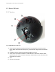
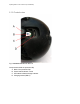
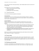
Fig 4. Top view Recce 360 mini
A. Power button/charger socket protection flap. When pressed this controls the power
button. When the flap is lifted (see figure 2), it exposes the charge socket and indicator
LED’s.
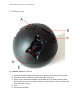
B. Orientation groove, a guide to quickly find the tether mount (C).
C. Tether mount. This holds a standard ¼-20 thread that can be used to attach a tether,
tripod mount, pole mount, or another accessory. Another tether mount is located on the
other side of the camera.
D. Lens
E. LED scene illumination.