
Datasheet


1
10
100
1000
10 ms
0.1 µs 1.0 µs
10 µs 100 µs 1.0 ms
t
d
- Pulse Width (Seconds)
I
PPM
- Peak Pulse Power (kW)
Non-repetitive pulse waveform
shown in Fig. 3
T
A
= 25 °C
Peak Pulse Power (P
PP
)
or Current (I
PP
) Derating (%)
100
80
60
40
20
0
050100 15
02
0025 75 125175
Case Temperature (°C)
Input Peak Pulse Current (%)
150
100
50
0
010203040
t - Time (ms)
t
r
= 10 µs
t
d
Peak value (I
PPM
)
Half value = I
PPM
T
J
= 25 °C
Pulse width (td)
is defined as the point
where the peak current
decays to 50 % of I
PPM
C
J
- Junction Capacitance (pF)
100,000
10,000
1,000
10 15 20 25 30 35 40 45
V
WM
- Reverse Stand-Off Voltage (V)
Measured at Zero Bias
T
J
= 25 °C
f = 1.0 MHz
V
sig
= 50 mV
p-p
Measured at
Standoff Voltage V
WM
Power Dissipation (W)
8.0
6.0
4.0
2.0
0
050100 150200
Case Temperature (°C)
Transient Thermal Impedance (°C/W)
100
10
1
0.1
0.01
0.01 0.1110 100
R
θJA
R
θJC
t - Pulse Width (s)
Specifications are subject to change without notice.
Users should verify actual device performance in their specific applications.
The products described herein and this document are subject to specific legal disclaimers as set forth on the last page of this document, and at www.bourns.com/docs/legal/disclaimer.pdf.
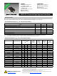
15KPA-SD-Q
Transient Voltage Suppressor Diode Series
Performance Graphs
Pulse Derating Curve
Peak Power Dissipation
Pulse Waveform Typical Junction Capacitance
Steady State Power Dissipation
Typical Thermal Impedance