
Datasheet


Features
■ RoHS compliant*
■ Low profi le is compatible with DIPs
■ Wide assortment of pin packages enhances
design fl exibility
■ Ammo-pak packaging available
■ Recommended for rosin fl ux and solvent
clean or no clean fl ux processes
■ Marking on contrasting background for
permanent identifi cation
4600X Series - Thick Film Conformal SIPs
*RoHS Directive 2002/95/EC Jan 27 2003 including Annex.
Specifi cations are subject to change without notice.
Customers should verify actual device performance in their specifi c applications.
Product Characteristics
Resistance Range
....................10 ohms to 10 megohms
Maximum Operating Voltage .........100 V
Temperature Coeffi cient of Resistance
50 Ω to 2.2 megohms ... ±100 ppm/°C
below 50 Ω .................... ±250 ppm/°C
above 2.2 megohms ..... ±250 ppm/°C
TCR Tracking ........................ 50 ppm/°C
maximum; equal values
Resistor Tolerance ............... See circuits
Insulation Resistance
................ 10,000 megohms minimum
Dielectric Withstanding Voltage
...........................................200 VRMS
Operating Temperature
............................... -55 °C to +125 °C
Environmental Characteristics
TESTS PER MIL-STD-202 ........ΔR MAX.
Short Time Overload ................ ±0.25 %
Load Life ................................... ±1.00 %
Moisture Resistance ................. ±0.50 %
Resistance to Soldering Heat
.............................................. ±0.50 %
Terminal Strength ..................... ±0.25 %
Thermal Shock ......................... ±0.25 %
Physical Characteristics
Flammability ........Conforms to UL94V-0
Body Material ...................... Epoxy resin
Standard Packaging
..................Bulk, Ammo-pak available
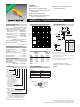
Package Power Temp. Derating Curve
How To Order
46 06 X - 101 - 222 __ LF
Model
(46 = Conformal
SIP)
Number of Pins
Physical Confi guration
(X = Thick Film Low Profi le)
Electrical Confi guration
• 101 = Bussed
• 102 = Isolated
• 104 = Dual Terminator
• AP1 = Bussed Ammo**
• AP2 = Isolated Ammo**
• AP4 = Dual Ammo**
Resistance Code
• First 2 digits are signifi cant
• Third digit represents the
number of zeros to follow.
Resistance Tolerance
• Blank = ±2 % (see “Resistance Tolerance”
on next page for resistance range)
• F = ±1 % (100 ohms - 5 megohms)
Terminations
• All electrical confi gurations EXCEPT 104 & AP4:
LF = Sn/Ag/Cu-plated (RoHS compliant)
• ONLY electrical confi gurations 104 & AP4:
L = Sn/Ag/Cu-plated (RoHS compliant)
Consult factory for other available options.
**Available for packages with 10 pins or less.
Product Dimensions
Package Power Ratings (Watts)
Ambient Ambient
Temp. Temp.
Pkg. 70 °C Pkg. 70 °C
4604X 0.50 4610X 1.25
4605X 0.63 4611X 1.38
4606X 0.75 4612X 1.50
4607X 0.88 4613X 1.63
4608X 1.00 4614X 1.75
4609X 1.13
Typical Part Marking
Represents total content. Layout may
vary.
For Standard Values Used in
Capacitors, Inductors, and Resistors,
click here.
WATTS
AMBIENT TEMPERATURE ( C )
°
0 70 125
3.50
3.00
2.50
2.00
1.50
1.00
.50
25
4612X
4608X
4606X
4614X
4604X
4610X
Part Number Marking
4606X-101-RC 6X-1-RC
4608X-102-RC 8X-2-RC
4610X-104-RC/RC 10X-4-RC/RC
RC = ohmic value, 3-digit resistance
code.
NUMBER OF PINS
6X-2-222
YYWW
CIRCUIT
RESISTANCE
CODE
PIN ONE
INDICATOR
MANUFACTURER'S
TRADEMARK
DATE CODE
A
MAXIMUM
PIN #1
REF.
5.08
(.200)
MAX.
3.3 +0.5/-0.3
(.130 +.020/ -.012)
1.24
(.049)
MAX.
BOTH ENDS
.508 ± .050
(.020 ± .002)
TYP.
2.54 ± .07
(.100 ± .003*)
TYP.
NON-ACCUM.
2.49
(.098)
MAX.
.254 ± .050
(.010 ± .002)
MAX.
Maximum package length is equal to 2.54mm (.100") times the
number of pins, less .005mm (.002").
Governing dimensions are in metric. Dimensions in parentheses
are inches and are approximate.
*Terminal centerline to centerline measurements made at point of
emergence of the lead from the body.
Pin A Maximum
Count mm (Inches)
4 10.11 (.398)
5 12.65 (.498)
6 15.19 (.598)
7 17.73 (.698)
8 20.27 (.798)
9 22.81 (.898)
10 25.35 (.998)
11 27.89 (1.098)
12 30.43 (1.198)
13 32.97 (1.298)
14 35.51 (1.398)
*RoHS COMPLIANT