
Datasheet

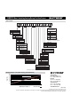

Rotational Life vs. Side Load
80
100
120
60
40
20
0
0 100 200
Shaft Side Load (grams)
Rotational Life (Millions of Cycles)
300 400 50050 150 250 350 450
Features
■ Non-contacting magnetic technology
■ Highly resistant to vibration/shock
■ Highly resistant to fl uid/dust ingress
■ Programmable at factory for zero position
■ Robust design for industrial applications
■ Highly repeatable
■ Dual ball bearing
■ RoHS compliant*
AMS22U Non-Contacting Analog Rotary Position Sensor
*RoHS Directive 2002/95/EC Jan. 27, 2003 including annex and RoHS Recast 2011/65/EU June 8, 2011.
Specifi cations are subject to change without notice.
The device characteristics and parameters in this data sheet can and do vary in different applications and actual device performance may vary over time.
Users should verify actual device performance in their specifi c applications.
Electrical Characteristics
1
(@ 25 °C)
VDD Supply Voltage ..................................................................................................5 V ± 10 %
Supply Current
2
For Low Speed Processing (Code L) ................................................................... 10 mA max.
For High Speed Processing (Code H) ................................................................. 20 mA max.
Output Signal (Single) ..................................................................................................... Analog
Independent Linearity ...................................................................................................... ±0.5 %
(±0.3 % available on request)
Hysteresis .........................................................................................................0.2 % VDD max.
Effective Electrical Angle
3
.................................................................................................. 340 °
Programmable Electrical Angle .................................................. 10 ° to 360 ° (10 ° increments)
Voltage Output (Programmable) ................................................................ 1 to 99 % VDD ±1 %
Output Resolution .................................................................................................12 bit @ 360 °
Load Resistance Recommended ....................................................................... 10K ohms to
∞
Overvoltage Protection .................................................................................................+20 VDC
Reverse Voltage Protection ...........................................................................................-10 VDC
Environmental Characteristics
Operating Temperature ......................................................................................-40 ° to +125 °C
Moisture Resistance .........................................................................MIL-STD-202, Method 106
Insulation Resistance @ 500 VAC..........................................................................500 MΩ min.
Rotational Life (Shaft Revolutions) ............................................................................ 100 million
Vibration ..............................................................................................................................15 G
Shock...................................................................................................................................50 G
IP Rating .............................................................................................................................. IP50
ESD Safe .................................................................................................................... 2 kV max.
Mechanical Characteristics (@ 25 °C)
Mechanical Angle ..................................................................................................... Continuous
Shaft/RPM .........................................................................................................1000 RPM max.
Torque (Starting & Running) ...........................................................1.06 N-cm. (1.5 oz-in.) max.
Shaft Material ...................................................................................................... Stainless steel
Terminals ................................................................. Brass / 100 % matte tin over Ni Strike (e3)
Bearing ............................................................................................................ Dual ball bearing
Soldering Condition
Manual Soldering ................................................. 96.5Sn/3.0Ag/0.5Cu solid wire or no-clean
rosin cored wire; 370 °C (700 °F) max. for 3 seconds
Wave Soldering .............................................. 96.5Sn/3.0Ag/0.5Cu solder with no-clean fl ux;
260 °C (500 °F) max. for 5 seconds
Wash Processes ........................................................................................Not recommended
1
At room ambient: +25 °C nominal and 50 % relative humidity nominal, except as noted.
2
See “Processing Speed” in How to Order selection guide.
3
Other Effective Electrical Angles available. See How to Order selection guide.
*RoHS COMPLIANT
Product Dimensions
+
S1
CW
S1 V
OUT
CCW
–
OUTPUT VOLTAGE INCREASES WHEN
SHAFT IS ROTATED IN THIS DIRECTION
(SEE HOW TO ORDER FOR
DIRECTION CODE)
12.7 ± 0.76
(.500 ± .030)
1.57 ± 0.10
(.062 ± .004)
1.57 ± 0.10
(.062 ± .004)
1.57 ± 0.10
(.062 ± .004)
3.167 +.000/-.025
(.1247 +.000/-.001)
DIA.
MAX. DIA.
3 PLCS.
3 PLCS.
0.51
(.020)
22.23
(.875)
DIA.
19.69
(.775)
MAX.
DIA.
5.08
(.200)
3 PLCS.
GND
(GROUND)
SIGNAL
(OUTPUT)
V+ SUPPLY
(INPUT)
4.06 ± 0.38
(.160 ± .015)
5.08
(.200)
5.08
(.200)
45 ° ± 5 °
1.02
(.040)
2.80 ± 0.10
(.110 ± .004)
0.51
(.020)
2.03
(.080)
1.55 ± 0.25
(.061 ± .010)
19.05 +.000/-.025
(.750 +.000/-.001)
19.69
(.775)
15.62
(.615)
+
–
V
DD
(5 V)
GND
3.18 +.000/-.025
(.125 +.000/-.001)
DIA.
DIA.
MIN.
2.67 +.000/-.076
(.105 +.000/-.003)
7.80
(.307)
FLATTED
OPTION
DIMENSIONS:
MM
(INCHES)
Schematic
Fig.
1