
Datasheet

Features
n Compliant with AEC-Q200 Rev-C- Stress
Test Qualification for Passive Components
in Automotive Applications
n 100 % electrically compatible with all
previous generations of 1812 SMT devices
n Compatible with Pb and Pb-free solder
reflow profiles
n RoHS compliant* and halogen free**
n Surface mount packaging for automated
assembly
n Agency recognition:
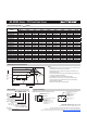
n Standard 4532 mm (1812 mils) footprint
n Patents pending
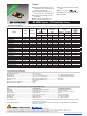
MF-MSMF Series - PTC Resettable Fuses
* RoHS Directive 2002/95/EC Jan. 27, 2003 including annex and RoHS Recast 2011/65/EU June 8, 2011.
**Bourns is using the definition that appears to be the prevalent definition used as the industry standard at this time. The Bourns definition of “halogen-free” is:
Bromine (Br) content: ≤ 900 ppm; Chlorine (Cl) content: ≤ 900 ppm; Total Br + Cl content: ≤1500 ppm.
Specifications are subject to change without notice. Users should verify actual device performance in their specific applications.
The products described herein and this document are subject to specific legal disclaimers as set forth on the last page of this document, and at www.bourns.com/docs/legal/disclaimer.pdf.
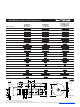
Model
V max.
Volts
I max.
Amps
I
hold
I
trip
Resistance
Max. Time
To Trip
Tripped
Power
Dissipation
Amperes
at 23 °C
Ohms
at 23 °C
Amperes
at 23 °C
Seconds
at 23 °C
Watts
at 23 °C
Hold Trip
R
Min.
R
1Max.
Typ.
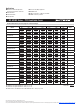
MF-MSMF010 60.0 40 0.10 0.30 0.70 15.00 0.5 1.50 0.8
MF-MSMF014 60.0 40 0.14 0.34 0.40 6.50 1.5 0.15 0.8
MF-MSMF020 30.0 80 0.20 0.40 0.40 6.00 6.0 0.06 0.8
MF-MSMF020/60 60.0 40 0.20 0.40 0.40 6.00 1.5 0.15 0.8
MF-MSMF030 30.0 10 0.30 0.60 0.30 3.00 8.0 0.10 0.8
MF-MSMF050 15.0 100 0.50 1.00 0.15 1.00 8.0 0.15 0.8
MF-MSMF050/30X 30.0 40 0.50 1.00 0.15 1.30 8.0 0.15 0.8
MF-MSMF050/40X*** 40.0 20 0.50 1.00 0.15 1.30 8.0 0.15 0.8
MF-MSMF075 13.2 100 0.75 1.50 0.11 0.45 8.0 0.20 0.8
MF-MSMF075/24 24.0 40 0.75
1.50 0.11 0.45 8.0 0.20 0.8
MF-MSMF110 6.0 100 1.10 2.20 0.04 0.21 8.0 0.30 0.8
MF-MSMF110/16 16.0 100 1.10 2.20 0.04 0.21 8.0 0.30 0.8
MF-MSMF110/24X 24.0 20 1.10 2.20 0.06 0.18 8.0 0.50 0.8
MF-MSMF125 6.0 100 1.25 2.50 0.05 0.14 8.0 0.40 0.8
MF-MSMF150 6.0 100 1.50 3.00 0.03 0.120 8.0 0.5 0.8
MF-MSMF150/12 12.0 100 1.50 3.00 0.03 0.120 8.0 0.5 0.8
MF-MSMF150/24X 24.0 20 1.50 3.00 0.03 0.120 8.0 1.50 1.0
MF-MSMF160 8.0 100 1.60 2.80 0.035 0.099 8.0 2.0 0.8
MF-MSMF200 8.0 40 2.00 4.00 0.020 0.080 8.0 2.0 0.8
MF-MSMF250/16X*** 16.0 100 2.50 5.00 0.015 0.100 8.0 5.0 1.2
MF-MSMF260 6.0 100 2.60 5.20 0.015 0.080 8.0 5.0 0.8
***TUV approval pending.
Electrical Characteristics
Test Procedures And Requirements For Model MF-MSMF Series
Test Test Conditions Accept/Reject Criteria
Visual/Mech. ......................................................... Verify dimensions and materials ........................... Per MF physical description
Resistance
............................................................ In still air @ 23 °C ................................................. Rmin ≤ R ≤ R1max
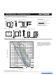
Time to Trip
........................................................... At specied current, Vmax, 23 °C ......................... T ≤ max. time to trip (seconds)
Hold Current
......................................................... 30 min. at Ihold ..................................................... No trip
Trip Cycle Life
....................................................... Vmax, Imax, 100 cycles ........................................ No arcing or burning
Trip Endurance
..................................................... Vmax, 48 hours ..................................................... No arcing or burning
Solderability
.......................................................... ANSI/J-STD-002 ................................................... 95 % min. coverage
UL File Number
.................................................... E174545 http://www.ul.com/ Follow link to Online Certicates Directory, then enter UL File
No. E174545, or click here
TÜV Certicate Number
....................................... R 02057213 http://www.tuvdotcom.com/ Follow link to “other certicates”, enter File No.
2057213, or click here
*RoHS COMPLIANT
*RoHS COMPLIANT
& AEC APPROVED
*RoHS COMPLIANT, **HALOGEN FREE
& AEC COMPLIANT
*RoHS and
AEC-Q200 COMPLIANT
LEAD FREE
*RoHS COMPLIANT
VERSIONS
AVAILABLE
LEAD FREE
VERSIONS ARE
RoHS COMPLIANT*
Environmental Characteristics
Operating Temperature
......................................... -40 °C to +85 °C
Passive Aging
....................................................... +85 °C, 1000 hours ............................................... ±5 % typical resistance change
Humidity Aging...................................................... +85 °C, 85 % R.H. 1000 hours
............................. ±5 % typical resistance change
Thermal Shock
..................................................... +85 °C to -40 °C, 20 times .................................... ±10 % typical resistance change
Solvent Resistance
............................................... MIL-STD-202, Method 215 ................................... No change
Vibration
............................................................... MIL-STD-883C, Method 2007.1, ........................... No change
Condition A
Moisture Sensitivity Level (MSL) .......................... Level 1
ESD Classication - HBM
..................................... Class 6