
Datasheet


60 ± 2
(2.362 ± .079)
178 ± 2
(7.008 ± .079)
13.5 ± 0.5
(.531 ± .020)
13.5 ± 0.5
(.531 ± .020)
DIA.
USER DIRECTION OF FEED
120 °
3.00 ± 0.1
(.118 ± .004)
0.26 ± 0.05
(.010 ± .002)
1.9
(.075)
R
13.5 ± 0.5
(.531 ± .020)
R
2 ± 0.5
(.079 ± .020)
4.90 ± 0.1
(.193 ± .004)
0.5
(.020)
R
10.5
(.413)
R
1.5 + 0.1
(.059 + .004)
DIA.
1.1 + 0.1
(.043 + .004)
DIA.
A
A
3.60 ± 0.1
(.142 ± .004)
SECTION A-A
12.0 ± 0.1
(.472 ± .004)
1.75 ± 0.1
(.069 ± .004)
5.5 ± 0.05
(.217 ± .002)
8.0 ± 0.1
(.315 ± .004)
4.0 ± 0.1
(.157 ± .004)
2.0 ± 0.05
(.079 ± .002)
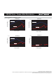
SRF0504 Series - Line Filter
Packaging Specifi cations
QTY: 500 PCS. PER REEL
REV. 06/13
Specifi cations are subject to change without notice.
The device characteristics and parameters in this data sheet can and do vary in different applications and actual device performance may vary over time.
Users should verify actual device performance in their specifi c applications.
SRF4532 Series - Common Mode Chip Inductors
DIMENSIONS:
MM
(INCHES)