XMS Studio Flash User Guide Bowens.co.
page left intentionally blank
Congratulations on purchasing your new Bowens product. Thank you for choosing the XMS range flash system. The Bowens XMS monolight has been designed by working closely with photographers to develop a unit that meets the exacting high standards demanded by today’s working professionals, while remaining simple and intuitive to use. The XMS range flash system is available in 500, 750 and 1000 Ws/Joules versions, all with integrated radio trigger and remote control functionality.
Bowens.co.
WARNING - Electrical Shock Hazard - High Voltage! • This unit should only be connected to a mains socket outlet with a protective earth connection or to a suitably protected battery/mains inverter. • Only use Bowens mains cables or extension cables. • The mains cable and plug is regarded as an emergency disconnect device and should always be readily accessible so that it can be quickly removed.
XMS user guide 6 Safety Instructions Environmental Safety • Do not place or use the unit where it could be exposed to moisture, dripping, splashing, extreme electromagnetic fields or in areas with flammable liquids, gases or dust. • Do not expose the unit to rapid temperature changes in humid conditions as this can lead to internal condensation.
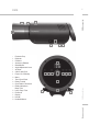
XMS 2 3 XMS user guide 7 4 1 6 5 8 17 9 10 11 12 13 14 15 6 18 19 XMS Appellation 16 Bowens.co.uk 1. Protector Cap 2. Reflector 3. S-Mount 4. Accessory Release 5. Stand Mount 6. Angle Adjustment Lever 7. AC Input 8. 3.5mm Jack Sync 9. Power: On / Standby 10. Menu 11. Test / Open Flash 12 . Rotary Control 13. Sync: Radio / Photocell 14. Ready Indications: Beep / Dim 15. Lamp: Prop / Free 16. Photocell 17. Display 18. Handle 19.
XMS user guide 8 Quick Start Guide The following is a quick guide to the individual controls, display and functions. Unless specified all push buttons operate as follow: • Press the button briefly to toggle the related function On or Off. • Press and hold the button to cycle through the options for the function. • Release the button when the required option is indicated.
Stand Mounting 1. Pull the Angle Adjustment Lever away from the main unit and extract the Stand Mount from the recess. 2. Push the Angle Adjustment Lever back in place to lock the Stand Mount in position. 3. Loosen the Stand Mount Thumb Screw on the Stand Mount and place the unit onto a support stand. 4. Rotate the unit into the desired position and fasten in place by tightening the Thumb Screw. 9 XMS user guide Quick Start Guide Head Angle Adjustment 1.
Operation XMS user guide Flash Output Setting Use the Rotary Control to change the flash output level. 1. The current flash energy is shown on the digital display in digital f-stops. All flash settings are related to the max setting (100%) which is shown as 10. 2. Turn the Rotary Control clockwise to increase the energy level in 1/10 f-stop increments, and counter-clockwise to decrease.
Modelling Light Free Setting continued. 3. While in FREE set mode, use the turn dial to change the FREE level. While an adjustment is being made it will stay in the FREE SET mode. 4. Adjust the turn-dial clockwise to increase the FREE level in 1/10 f-stop increments, and counter-clockwise to decrease. Press and hold down the turn-dial while turning to increase or decrease the setting in 1 f-stop increments. 5.
XMS user guide 12 Operation Ready Indication Setting continued. 4. To turn off the READY indications, briefly press the READY Button. Both the indicators will be turned off. 5. Briefly press the READY button again to turn the ready indications back on. Photocell The XMS photocell allows the unit to be triggered by another flash unit. The photocell is specially designed to work under studio light conditions. Direct light or other strong light sources may reduce the sensitivity of the cell.
Sync Source Setting continued. 2. To select the Pre-flash photocell, press and hold down the SYNC button until only the CELL Indicator is illuminated. The unit will be triggered by an infrared (IR) light pulse received from another flash unit or other pulsed light source but only after a pre-set number of flashes have been received in a pre-set time frame (see page 15). This allows the unit to ignore any pre-flashes produced by the camera. 3.
User Options XMS user guide User Menu Use the MENU button to access various settings to allow function customisation of the unit. Review and Adjustment 1. Select the required option by pressing the MENU button. Hold the MENU button down to advance quickly through the options. 2. Release the button when the desired option is displayed. 3. The displayed option will be shown alternating with its value. 4. Review or change the option value as required by using the Rotary Control.
Pairing (Pr) This option allows the unit to be paired or un-paired with an XMSR as well as allowing all pairing associations to be cleared. Refer to the XMSR Radio Trigger and Remote Control section. 15 XMS user guide User Options Remote Channel (Ch) This allows selection of the radio remote channel for this unit. Note that when the radio is selected on units, the flash on ALL units using the same channel will be triggered regardless of the Group setting.
User Options XMS user guide Pre-Flash Number (Pn) continued: 6. To exit the Auto mode if no flashes have been detected then either: a) Select a Pre-flash setting greater than 0. b) Choose another option and then allow the options display to time out. The Pre-flash value will be set to 1 (single main flash only). c) Press the TEST button to exit immediately. The Pre-flash value will be set to 1 (single main flash only).
Controls Sounder (So) Use this option to select the beep sounder to ‘Off, Warnings only, Button clicks only, or Both’. Note that the sounder will still produce a ‘ready’ beep regardless of this setting if the ‘ready’ beep is enabled. 17 XMS user guide User Options Lamp Saver (LS) This feature can be used to automatically dim the lamp to a minimum after a period of inactivity. It reduces the power consumed and any heat build up within the unit, and can also extend the life of the bulb.
User Options XMS user guide Power Switch State (PS) This option allows the last state of the Standby/Power switch to be remembered if power to the unit is suddenly lost. Set this option to 0 (Off) to always power up in Standby or 1 (On) to remember the last Power Switch state. When set to on and power is lost and then restored, the unit will continue to operate in the same state that it was in before the power was lost.
General The built-in XMSR radio trigger and remote control system is designed to be secure and interference tolerant. It allows the unit to be triggered and most functions to be controlled remotely. Refer to the instructions for the XMSR Remote Control. 19 XMS user guide XMSR Radio Remote & Trigger To enable an XMS and a remote control to communicate they need to be ‘paired’ together.
XMSR Radio Remote & Trigger XMS user guide Pairing With a Master (Pr/nP): Pr=pair / nP=new pair 1. Ensure both the XMSR and XMS units are switched on and in fairly close proximity so that the two displays can be seen. 2. On the XMS unit press the MENU button until the display shows ‘Pr’ to indicate ‘Pairing’ mode. The display will alternate between showing ‘Pr’ and ‘nP’ for ‘new pair’. 3. Press the Rotary Control to request pairing with the XMSR. 4.
Clearing All Pairing Associations (Pr/CP): Pr=pair / CP clear pairs The XMS can be cleared of associations with ALL XMSR remotes without needing a remote. This can be useful if the XMS was originally ‘paired’ with a remote that is no longer available. Note that ALL pairing will be lost. 21 XMS user guide XMSR Radio Remote & Trigger 1. On the XMS unit press the MENU button until the display shows ‘Pr’ to indicate ‘Pairing’ mode. 2.
User Maintenance XMS user guide Modelling Lamp Fitting 1. Before fitting or removing a modelling lamp, always ensure the power is switched off and remove the mains cable from the unit. 2. Avoid touching the flashtube and glass envelope of the modelling bulb with bare fingers as this can leave grease on the glass which can shorten the life of the bulb. 3. Select the correctly rated modelling bulb for the local mains supply. 4.
Warnings Warning and Error Management The XMS is fitted with a comprehensive monitoring system to detect any missoperation. If the display shows a Warning or an Error code and it does not automatically clear itself in a reasonable time then switch the unit to standby and back on again to see if it then clears. XMS user guide 23 Warnings: are normally only given because of transient problems. These normally reset automatically either shortly after the warning or after a period in the case of overheat.
Warnings XMS user guide OH indication continued: CONDITION STEPS TO RECTIFY Flash rate excessively fast: Reduce the flash rate and/or only flash at a fast rate in blocks with longer cooling periods in between. Fan not running or slow: Unit requires repair. OH does not clear: Unit requires repair. Radio Fault If there is a fault with the radio system then the RADIO LED will blink when the radio sync source is selected.
Specifications XMS500 Specifications Energy (Ws/J) 500 Power Range (f-stops) 7 Power Range (Ws/J) 7.8 - 500 Power Range (Fraction) 1/1 - 1/64 Flash Duration (t=0.5) f4.0 - f8.7 = 1/2480 - 1/5180 f8.8 - f10 = 1/3080 - 1/4000 Recycle Time Range @ 230V 50Hz 0.2 (min) - 1.0 (max) sec. @ 120V 60Hz 0.2 (min) - 1.5 (max) sec. Replacement flashtube (part code) BW3000 Weight 3.7kg / 8.
XMS user guide 26 Specifications Features common to all units Specifications Power Increments (f-stop) 1/10-stop or 1-stop Flash to flash consistency (f-stop) ±0.
page left intentionally blank
Bowens International Ltd. Gilberd Court, Colchester, Essex, CO4 9WN, UNITED KINGDOM. email: info@bowens.co.uk tel: +44(0)1206 832650 Bowens.co.