
Operation Manual


PVC (polyvinyl chloride) insulation for normal
use and fluoropolymer (Teflon) insulation for
plenumrated cable. We recommend the latter
for CASA™ in-wall and ceiling installations.
T h e re are no twists in the cables which are
w i red straight through. The only criterion is
that the pairs are adjacent, for example:
B rown is alongside Brown/White; Blue is
alongside Blue/White and Green is alongside
G reen/White, etc.
RJ-45 CONNECTOR PIN
ASSIGNMENT
( F i g u re 3)
The pin assignment for the RJ-45 connector
(Speaker connections):
Pin Signal C o m m e n t
1 +24/+12V 12V in Standby mode
2 –24/–12V 12V in Standby mode
3 as 1
4 as 2
5 as 1
6 as 2
7 + Audio
8 – Audio
9 0V S c re e n
LOADING CONSIDERAT I O N S
I n t e rface loading is governed by the perm i t t e d
number and type of speakers on any one
i n t e rface. The loading of speakers for one
I n t e rface is as follows:
• 1 pair of AW M ™ 7 0 s
• 2 pairs of AW M ™ 6 5 s
• 5 pairs of ACM™60s
Exceeding this loading will not render an
installation unsafe. The effect will be that
all speakers cannot be played at maximum
power output simultaneously.
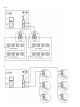
C O N N E C T I O N S
( F i g u re 4)
All connections should be made with the
equipment switched off. Connect the audio
s o u rce – such as a preamplifier or surro u n d
sound processor – to the RCA type phono
sockets. Connect the RJ-45 terminated STP
C a t e g o r y 5 speaker cables to the RJ-45 sockets.
I n f r a red remote signals picked up by speakers
connected to the Interface are present at the
mono 3.5mm jack at the rear of the Interf a c e .
This socket is designed to drive third party IR
window emitters with its output of 5V. The
modulation frequency of the IR output signal will
be approximately 38kHz irrespective of the
modulating frequency of the original re m o t e
c o n t ro l .
CONNECTIONS FOR ADDING
S P E A K E R S
Additional Speakers
( F i g u re 5 & 6)
Additional speakers can be connected using
RJ-45 T-pieces or to the socket marked
‘2nd Speaker’ on the ACM™60. The total
loading should not be exceeded if simultaneous
maximum volume levels are re q u i red – see
section Loading Considerations.
4