
Use and Care Manual


115
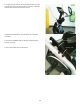
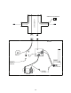
Brake Magnet
Flywheel
Tension Spring
Brake Arm
Servo Motor Bracket
Speed Sensor Cable
Servo Motor Cable
Lower Input/Output
(I/O) Cable
Potentiometer
Power Inlet
Cable
18. Measure and mark the position of the Servo Motor Bracket on the
Main Frame.
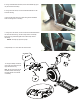
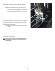
19.Insert2.5”x10”cardboardbetweentheBrakeMagnetandthe
Flywheel, and tape the cardboard to the Brake Magnet.
Note: Be sure the cardboard covers all of the Brake Magnet.
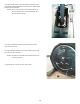
20. Observe the cable routing to the wiring harness on your machine.
Disconnect the Speed Sensor Cable and Servo Motor Cable from the
wiring harness.
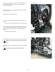
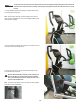
21.TiethelengthofstringtotheendoftheInput/Output(I/O)Cableatthe
top where the Console Mast attached. Remove the zipties that attach the
I/O Cable to the Frame. Pull the cable and string down through the hole
onthesideoftheFramesothatthestringextendsthroughtheFrame.
NOTICE: Hold the Lift Motor Cable so that you do not pull it out of
the Mast. Do not crimp the cables.
22. Untie the string from the I/O Cable Cable.
Input/Output (I/O) Cable
Lift Motor Cable