
Use and Care Manual


117
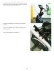
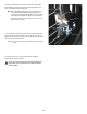
30. Pull back on the Brake Arm enough to clear the Motor Pulley Shaft.
Move the Brake Arm toward the new Servo Motor and gently allow it to
come to rest against the Motor Pulley Shaft.
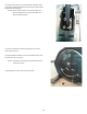
Note: Before fully attaching the Shrouds, remove the cardboard
from between the Brake Magnet and the Flywheel. Power
up the machine to verify that the Magnet Arm can move freely,
and that the Brake Magnet and Flywheel do not touch at the
maximumresistancelevel.Ifnecessary,refertothe“Setthe
Brake Tension” procedure.
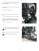
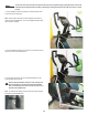
31. Re-assemble the machine in the reverse order of when the parts were
removed.PuttheLeftShroudinpositionrsttoalignthescrewsforthe
RightShroud.Installthetopscrewsrst.BesurethetabsintheMotorized
Lift Cover snap into the Side Shrouds.
NOTICE: This step may require two people. Be sure not to crimp any
cables.
32. Inspect your machine to ensure that all hardware is tight and
components are properly assembled.
Do not use until the machine has been fully assembled and
inspected for correct performance in accordance with the
Owner’s Manual.
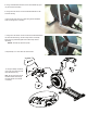
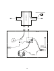
Brake Magnet
Flywheel
Motor Pulley
Shaft
Tension Spring
Brake Arm