
Use and Care Manual


138
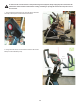
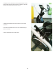
18. Measure or mark on a piece of scrap paper the length from the end
of the Tensioner Bolt to the outer Tensioner Nut. This will assist with re-
assembly.
19. Using a 10mm wrench, loosen and remove the outer Tensioner Nut so
the Tension Bolt can be released from the Tensioner Bracket.
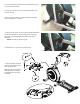
20.Usinga6mmhexwrenchanda13mmwrench,removetheTensioner
AssemblyHardware(A)thatattachestheTensionerAssemblytothe
Frame Upright.
Note:Usethehexwrenchtoholdthebolt(A)inplaceontheoutside
and turn the nut from the inside.
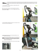
21. Remove the Tensioner Assembly from the Frame Assembly and the
Drive Belt.
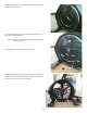
22. Install the new Tensioner Assembly routing the Drive Belt correctly.
Secure the hardware.
Note:BesuretoadjustthereplacementTensionerBoltandTen-
sioner Nuts to the previous length.
Note: Your machine may not match the image. For reference only.
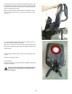
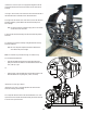
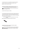
23.TotesttheDriveBelttension:
• PushtheDriveBeltdownwardatthemidpoint(M)betweenthe
pulleys and measure the distance. The Drive Belt should have only
0.25”(0.64cm)ofgive.
Or:
• HoldtheedgesoftheDriveBeltatthemidpoint(M)andtwistit.The
DriveBeltshouldturnonly90degrees(1/4turn,tovertical).
If the tension is correct, go to Step 27.
If the tension is too loose or too tight, adjust the nuts and bolt on the
TensionerAssembly(IdlerAssembly).
24.ToadjusttheTensionerNutsontheTensionerBracket,usea10mm
open end wrench to hold the Tensioner Bolt steady and turn the nuts with
a second 10mm open end wrench.
Tensioner Assembly
Tensioner Bracket
Tensioner
Nuts
Tensioner
Bolt
M
M
0.25”
0.64 cm
}
A