
Use and Care Manual


24
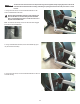
Note: Your machine may not match the image. For reference only.
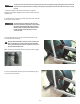
6.TotesttheDriveBelttension:
• PushtheDriveBeltdownwardatthemidpoint(M)betweenthe
pulleys and measure the distance. The Drive Belt should have only
0.25”(0.64cm)ofgive.
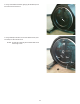
Or:
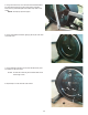
• HoldtheedgesoftheDriveBeltatthemidpoint(M)andtwistit.The
DriveBeltshouldturnonly90degrees(1/4turn,tovertical).
If the tension is correct, go to Step 10.
If the tension is too loose or too tight, adjust the nuts and bolt on the
TensionerAssembly(IdlerAssembly).
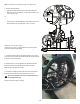
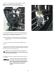
7. To adjust the Tensioner Nuts on the Tensioner Bracket, use a 10mm
open end wrench to hold the Tensioner Bolt steady and turn the nuts with
a second 10mm open end wrench.
8. When the tension is correct, tighten the nuts against the Tensioner
Bracket to hold the bolt and the Tensioner Assembly in position.
Note: This step may require two people.
9. Carefully turn the Right Crank Arm and check the movement of the
Drive Belt. The Crank Arms and Flywheel should move as one.
!
Be sure to keep ngers clear of all pinch hazards when you
turn the Right Crank Arm.
Adjust the belt tension again if necessary.
M
M
0.25”
0.64 cm
}
Tensioner Assembly
Tensioner Bracket
Tensioner
Nuts
Tensioner
Bolt