
Use and Care Manual


56
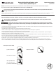
18. Measure or mark a piece of scrap paper the length from the end of
the Tensioner Bolt to the outer Tensioner Nut. This will assist with re-
assembly.
19. Using a 10mm wrench, loosen and remove the outer Tensioner Nut so
the Tension Bolt can be released from the Tensioner Bracket.
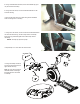
22.Usinga6mmhexwrenchanda13mmwrench,loosentheTensioner
AssemblyHardware(A)thatattachestheTensionerAssemblytothe
Frame Bracket.
Note: Usethehexwrenchtoholdtheboltinplaceontheoutsideandturn
the nut from the inside.
21. Turn the Drive Pulley clockwise while forcing the Drive Belt to the
outside to remove it. The belt will come off of the Drive Pulley.
Keep ngers out of any pinch hazards when turning the
Pulleys.
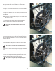
22.Toremovetheindicatedhardware(byoval)fromtheFlywheel,usea
17mm open end wrench to hold the nut on one side steady and remove
the nut on the opposite side with the 17mm socket and wrench. Set the
hardware safely aside.
23. Adjust the angle of the Tensioner Assembly to allow the Flywheel to
move forward. Remove the Flywheel from the Frame Brackets and the
Drive Belt.
The Flywheel is heavy. This step may require two people.
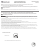
24.RemovetheoldDriveBeltafternotinghowtoproperlyroutethenew
Belt.
25. Hold the Flywheel near the Frame Brackets and put the new Drive Belt
in position on the Flywheel Pulley. Put the Drive Belt in position around
the Tensioner Assembly. Be sure that the upper portion of the Drive Belt is
under the Tensioner Bearings on the Tensioner Assembly.
The Flywheel is heavy. This step may require two people.
Tensioner Assembly
Tensioner Bolt
Flywheel
Frame Bracket
Tensioner
Bracket
A
Drive Belt
Tensioner Nuts
Tensioner Assembly
Tensioner Bolt
Flywheel
Tensioner
Bracket
Tensioner Nuts